I know exactly how you feel… I keep a bunch of unusable PCBs (too many kludges required) on hand to remind myself not to made the mistake of ordering more than the minimum number of PCBs for untested prototypes 
3 Likes
Ughh, that’s got to hurt 
Hopefully you can find an easy work around & haven’t ordered too many of them.
I made some some progress. traced the bug and cut the copper.
There is noise output now. SO I’m going to check the rest of the circuit.
I had some new ideas about the filters, so I might add those, we’ll see
6 Likes
Most outputs work, except for the comparator output.
I will work on that. The 1st prototype worked, so it is probably something easy to fix
the noise range is pretty nice, lots of cool textures !
6 Likes
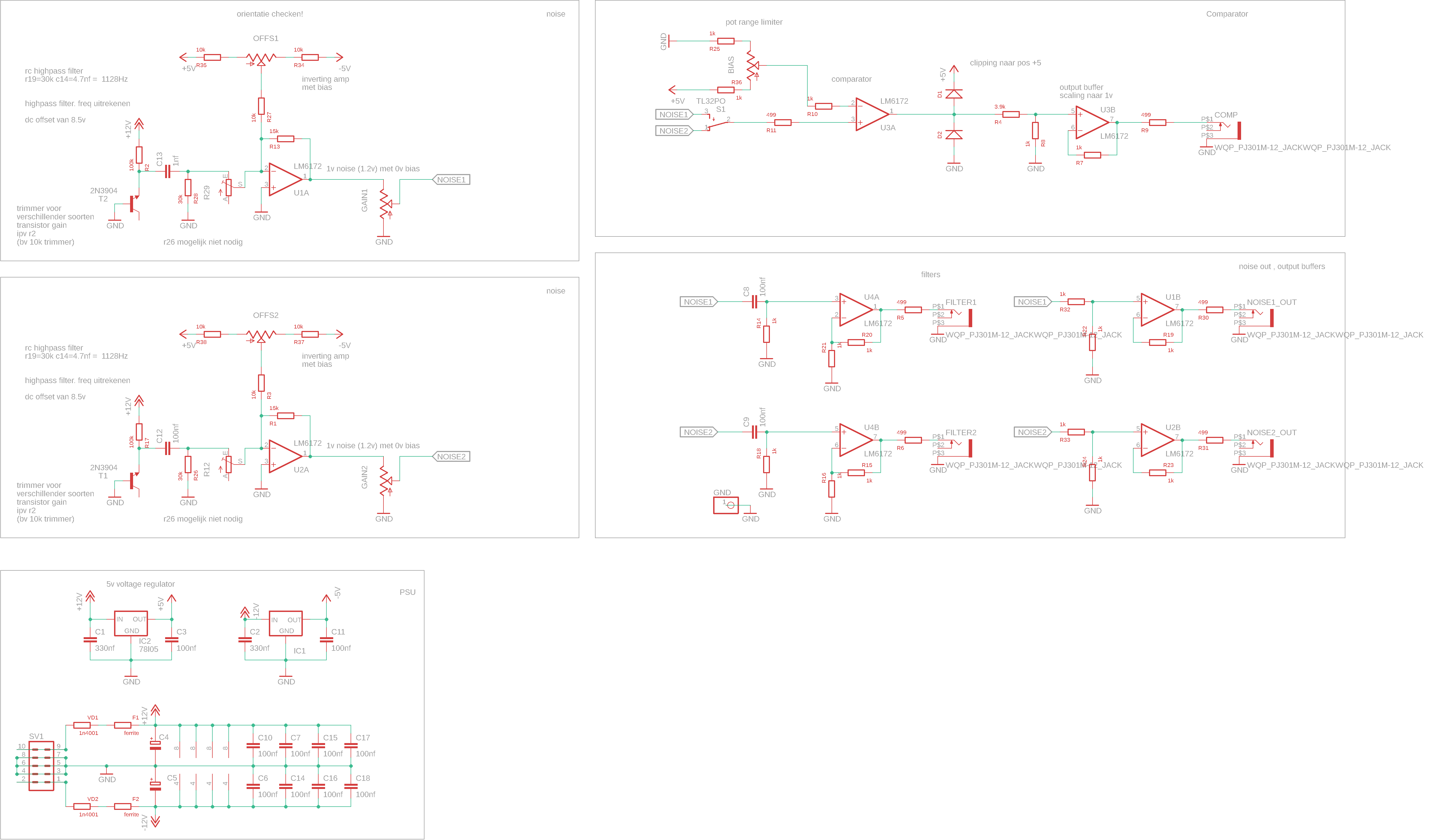
Do you have an updated schematic to look at?
It looks like you have +12V connected to the input of your 7905 regulator. Negative in, negative out.
Also, for the diode clipper portion to work effectively, there needs to be a resistance before the diodes.
2 Likes
Forgive my ignorance, but I’m curious if this noise overlaps audio/sub ranges in a useful way. My system has become a hybrid of audio and video - it’s great to be able to swap modules for such different uses and I’m often looking for these opportunities.
1 Like
yes, that 7905 thing was the bug stupid
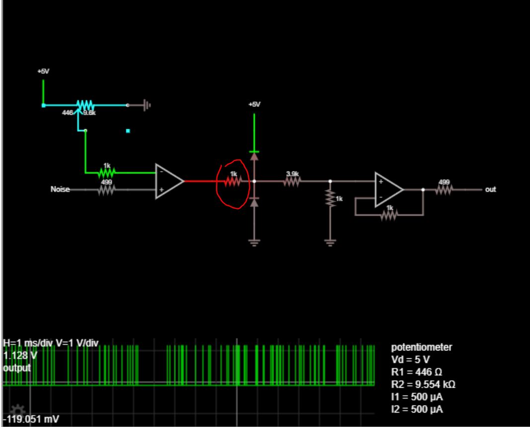
I’ll look into the diode tip, thanks … The simulation worked, but reality is different 
2 Likes
I have not listened to it yet. The output is about 1v, so you would need to amplify it to audio levels
You can set the frequencies of the filters by the resistor + capacitor, so it would be possible to scale that to audio ranges. I’ll make a note of this when I write the buildguide
The offset knobs won’t give you useful audio results though.
2 Likes
Your simulation has the resistor between the op amp and diodes, but your schematic doesn’t.
Without a resistor, the full current from the op amp conducts across the diode. I think diodes in this situation may even “latch up” but I have to read more about that.
What kind of signal are you seeing with the current schematic? Hotter than 0/+1v? DC?
There is another option to consider which doesn’t use diodes. This requires you power that LM6172 with +/-5v and add a few resistors at the output. Ideally the output bounces between -5v and +5v. R18 and R19 create a voltage divider when the op amp outputs -5v only. So the junction between R18 and R19 will only be 0v and +5v.
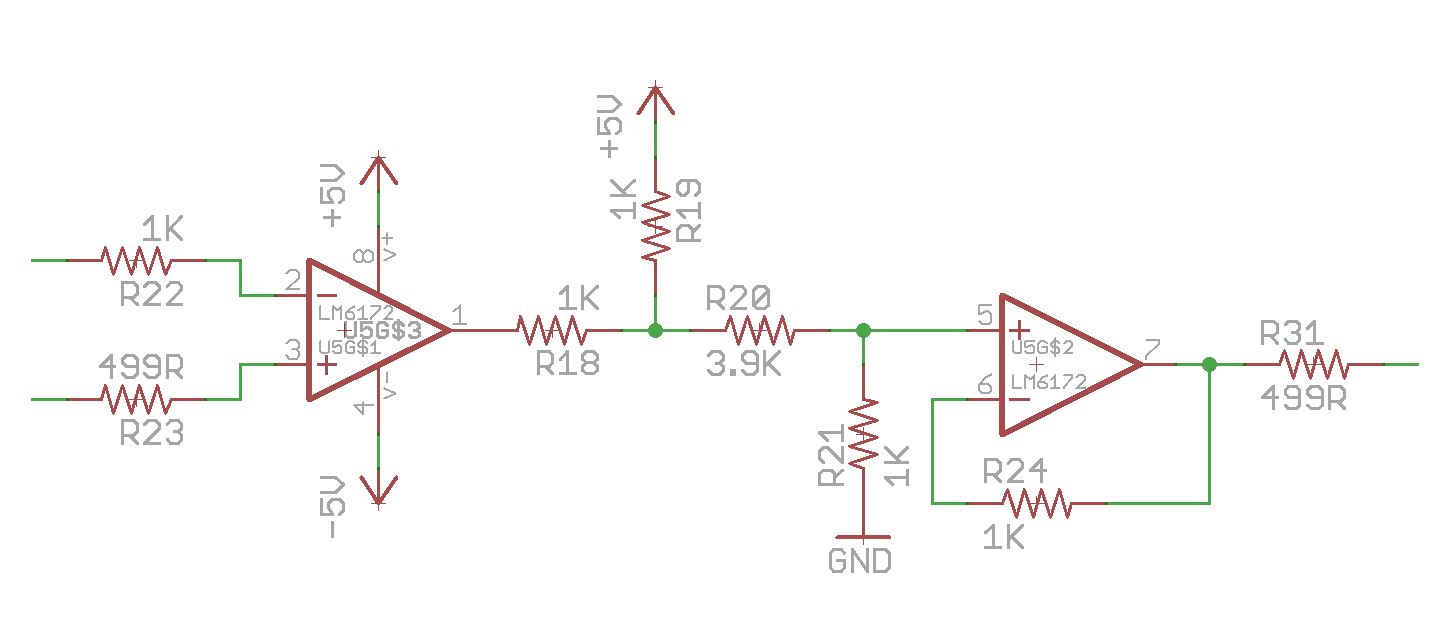
This is effective, but has one drawback. The op amp will not output exactly -5v and +5v, but will instead be closer to -3.35v and +4.14v (according to my simulation in LTspice). So the final output will be +140mV to +840mV with these resistor values. While this is not “full” brightness, these voltages ‘will’ at least trigger comparators that use a reference of 500mV like much of the Castle series.
I think if you want a full-brightness digital noise output that clips at exactly 0/+1v, you may need to use the more precise clipper circuit you see in Cadet II.
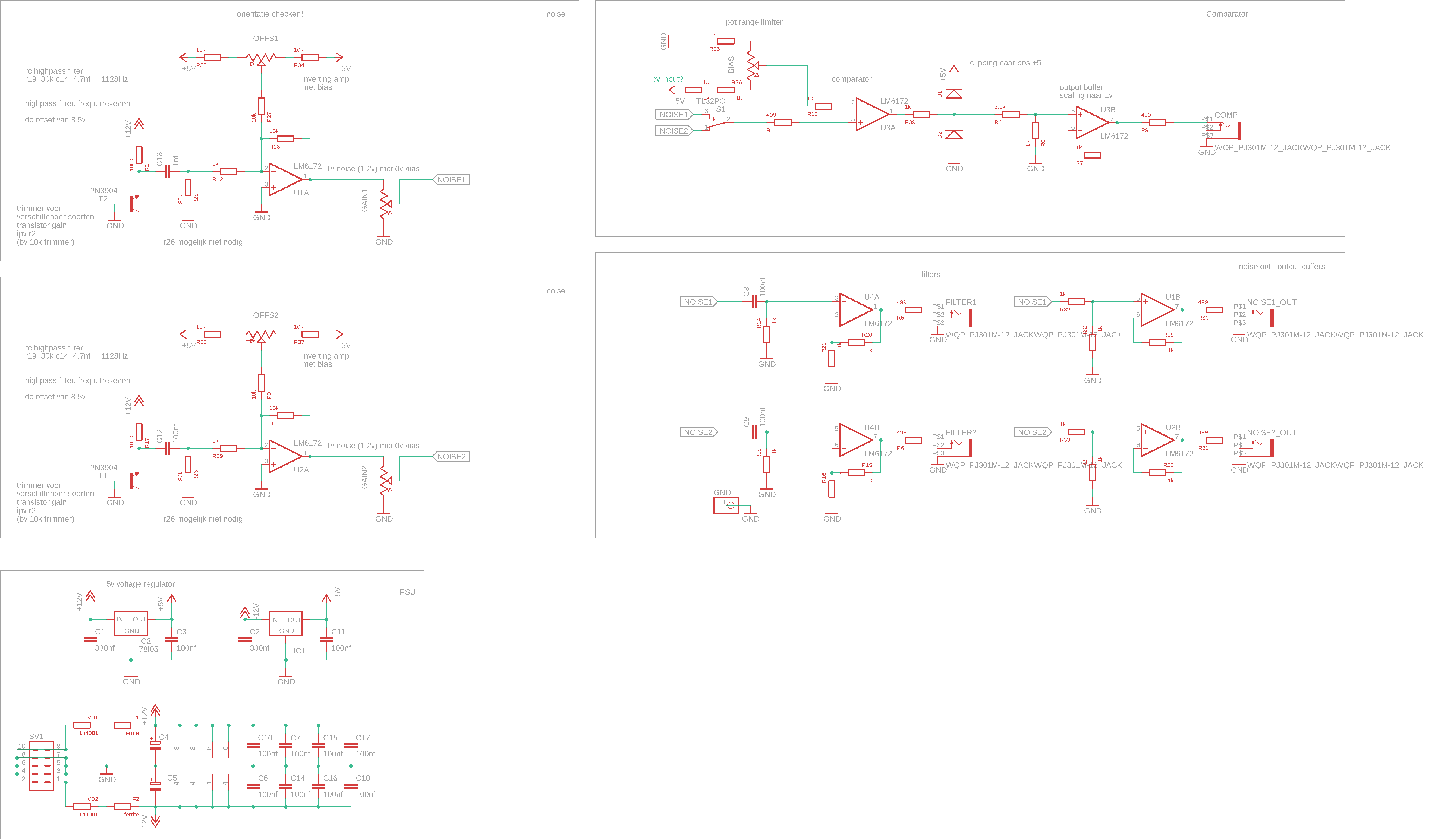
Would you mind cutting/adding in the resistor here and let us know if you see better results?
4 Likes
I should have looked to my simulation better !
Thanks for the detailed advice. I will do some more testing after the weekend and report back here.
The comparator jack has no output on my CRT, I’ll check again with scope for precise measurements
3 Likes
I ordered a new prototype with these fixes.
8 Likes
the pcbs are in. I’ll start testing this week!
11 Likes
test update:
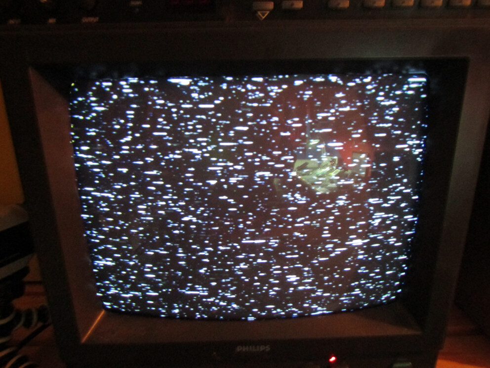
the comparator works very good!
it can go from black starfield to white blizzard, so it lives up to its name!
channel 2 noise looks nice
I have to adjust some values for amplification settings (channel 1)
The values I calculated for filters might be off, so I’m going to test what works better!
quick and dirty screen photos of the comparator out:


15 Likes
this is looking lovely!
1 Like
This looks sweet! Nice use of 8hp
1 Like
OK testing is done!
Turned out I had a faulty lm6172 in my testbuild. replaced it and now everything works as intended!!

I’ll make a [ORDER] thread. I have about 8 pcbs left, I’ll order more this week!
I’ll try to make a demo soon!
7 Likes