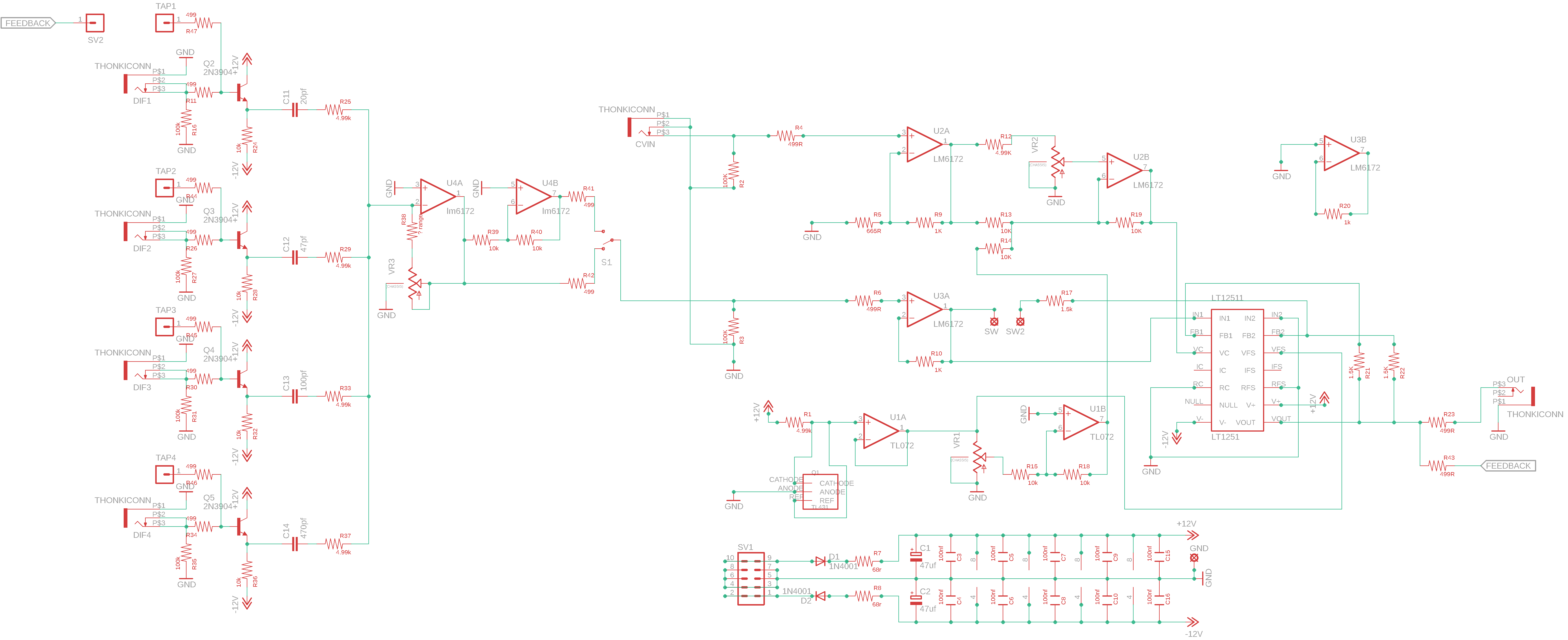
So, I want to make a Differentiator pcb with additional voltage controlled feedback.
I normally feedback it with a summing mixer, but I think CV control will make it even more interesting.
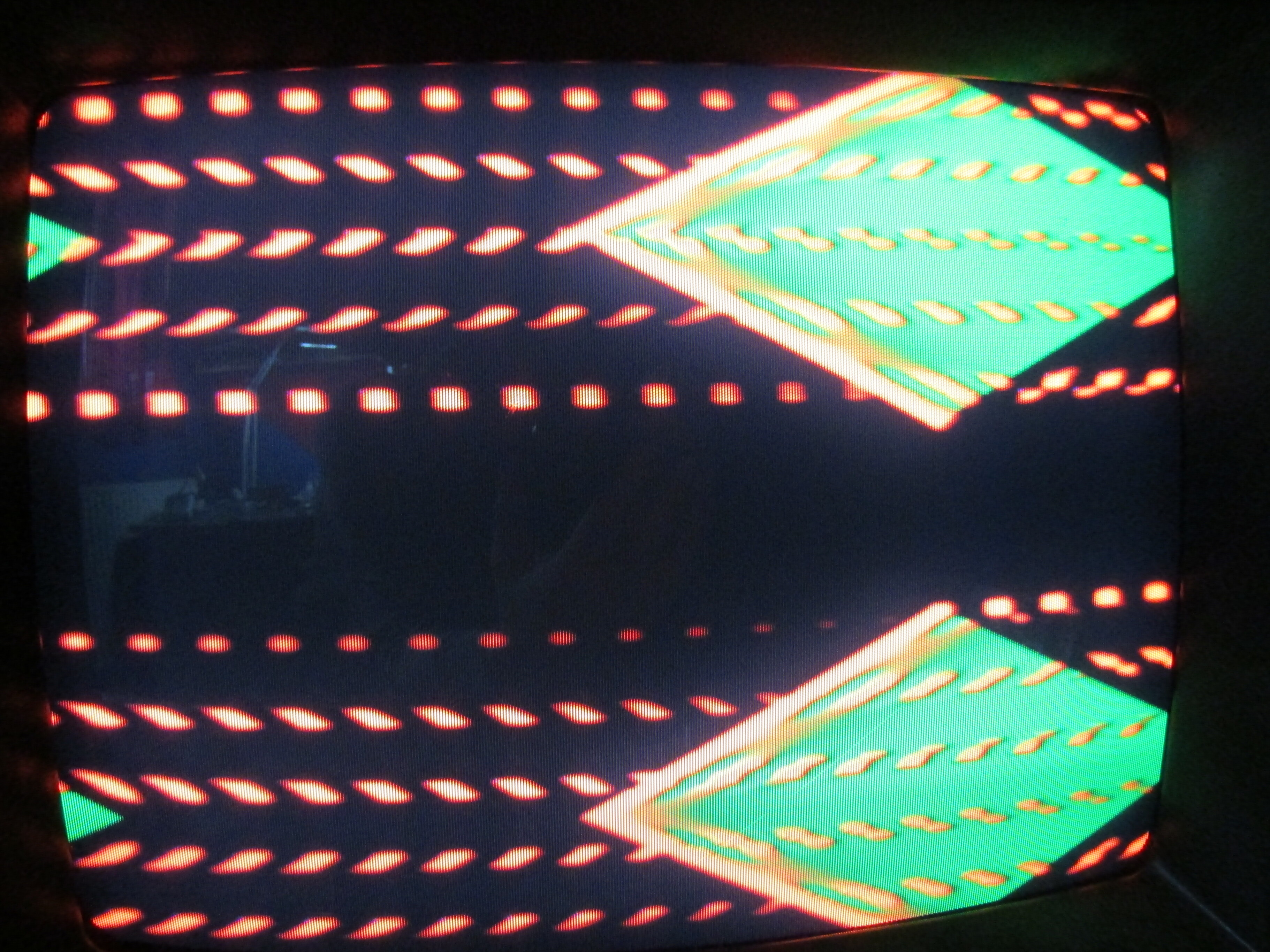
The effect of the feedback is that the edges repeat themselves several times until chaos ensues.
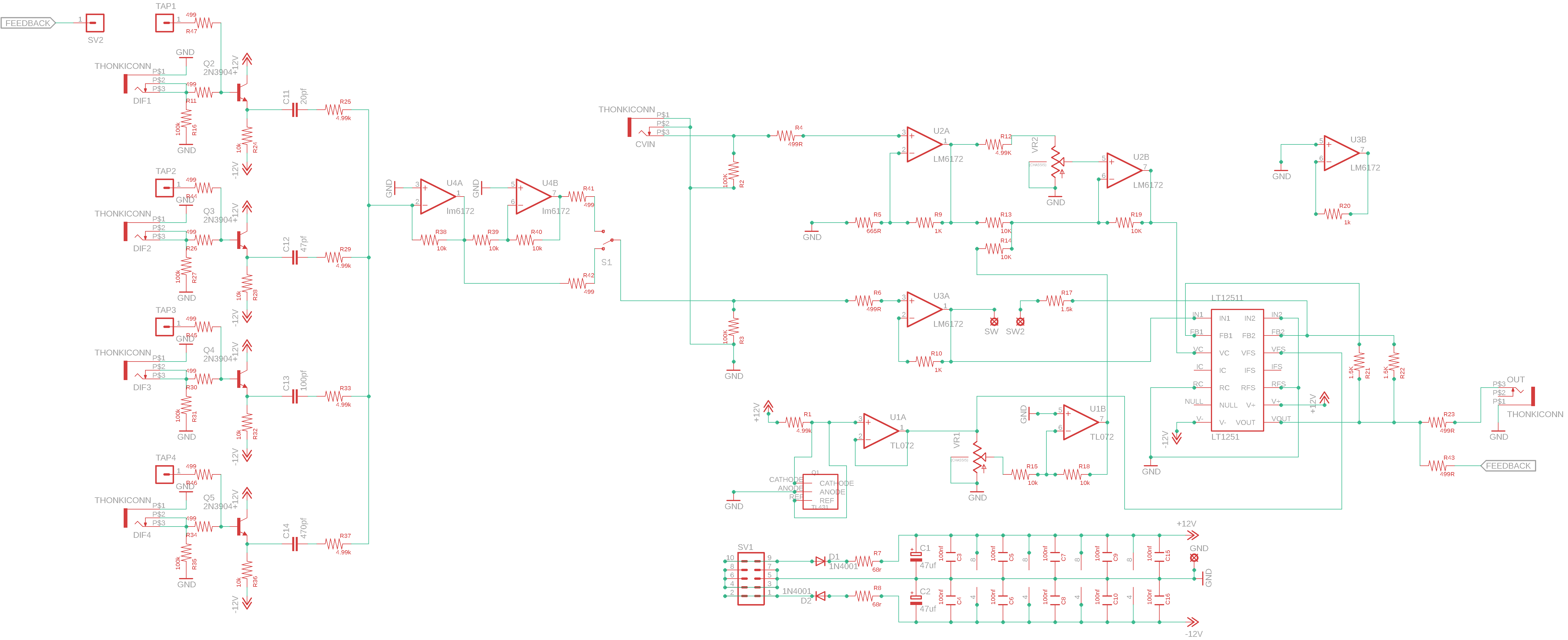
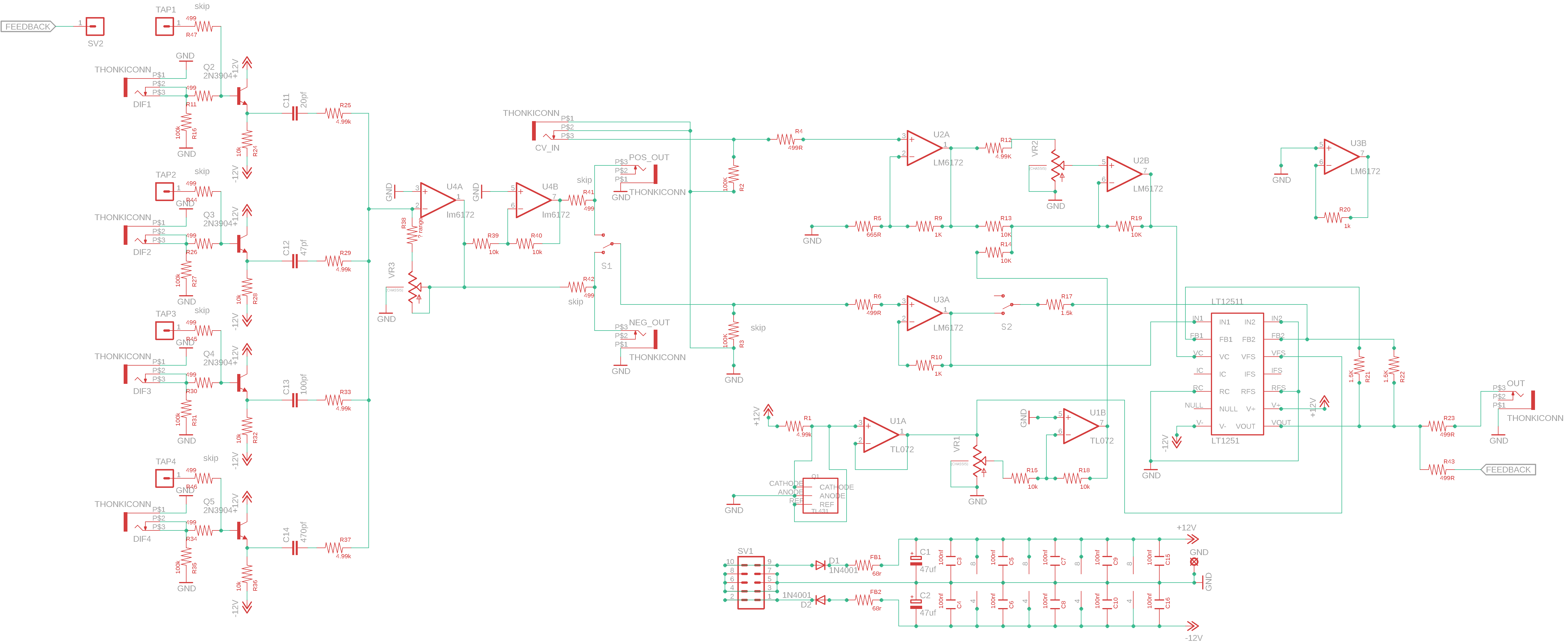
I paired the Cadet Multiplier schematic with the Differentiator and changed some stuff
The design is not finished yet and must be tested.
Right now I’m thinking 1 pcb for pots and jacks, 1 pcb for the main circuit and a panel pcb.
All sandwiched together to decrease depth. 8HP if it fits
feedback path switch (normal / inverted) - be to tested
4 edge filter inputs (instead of 6) - to save space. If it fits, this can be changed to 5 or 6.
switches for feedback routing
not added yet, but interesting: diode clipping distortion or more filtering in the feedback path?
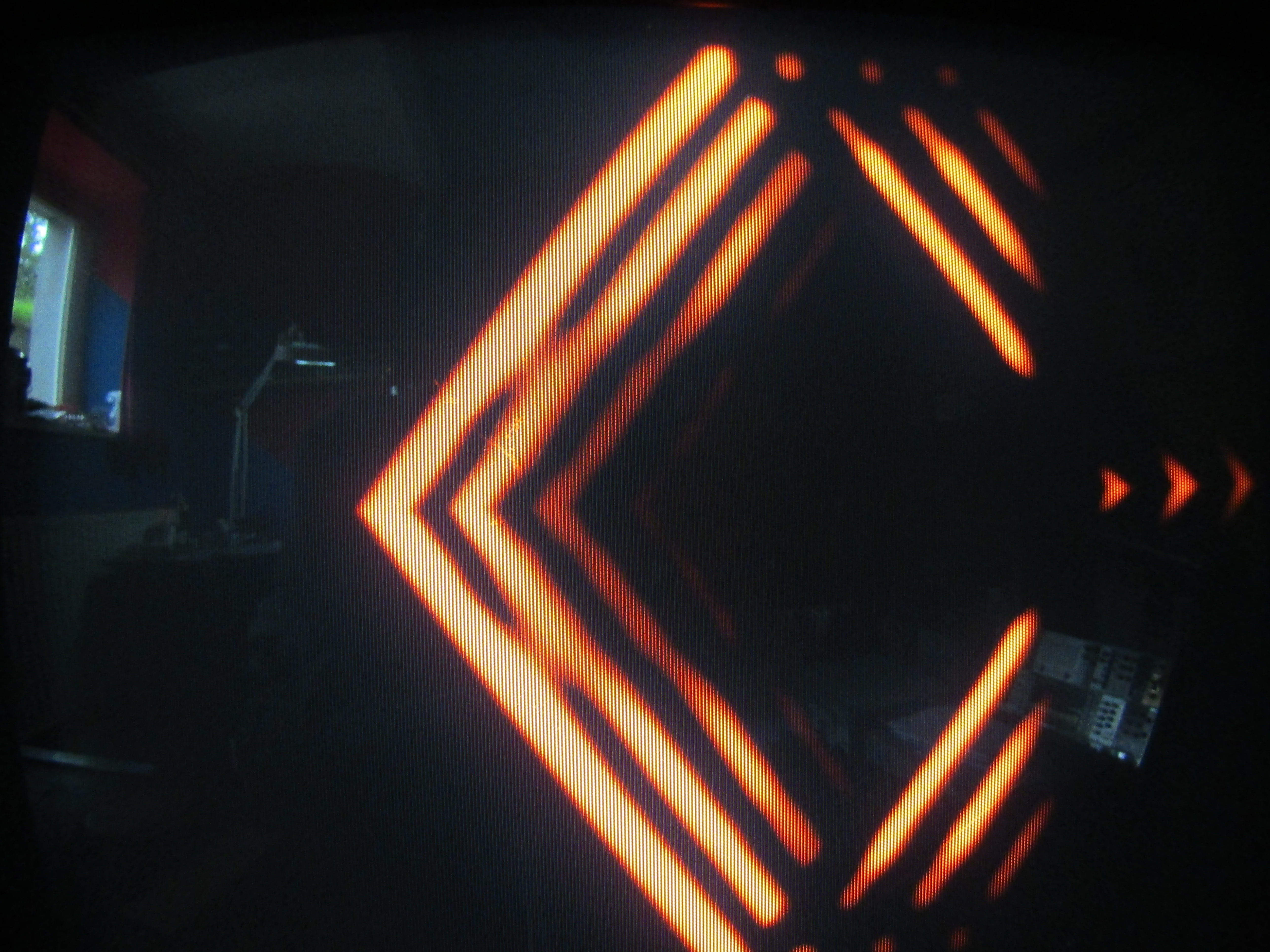
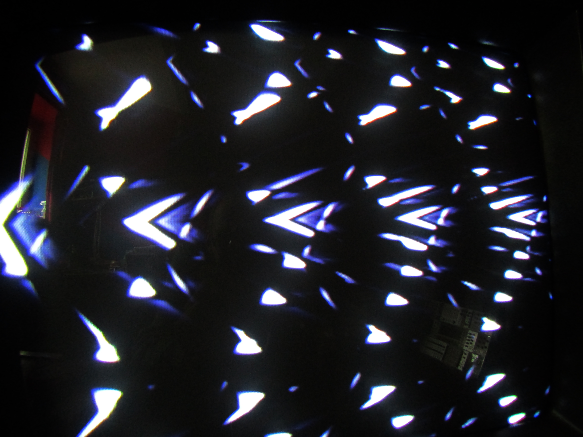
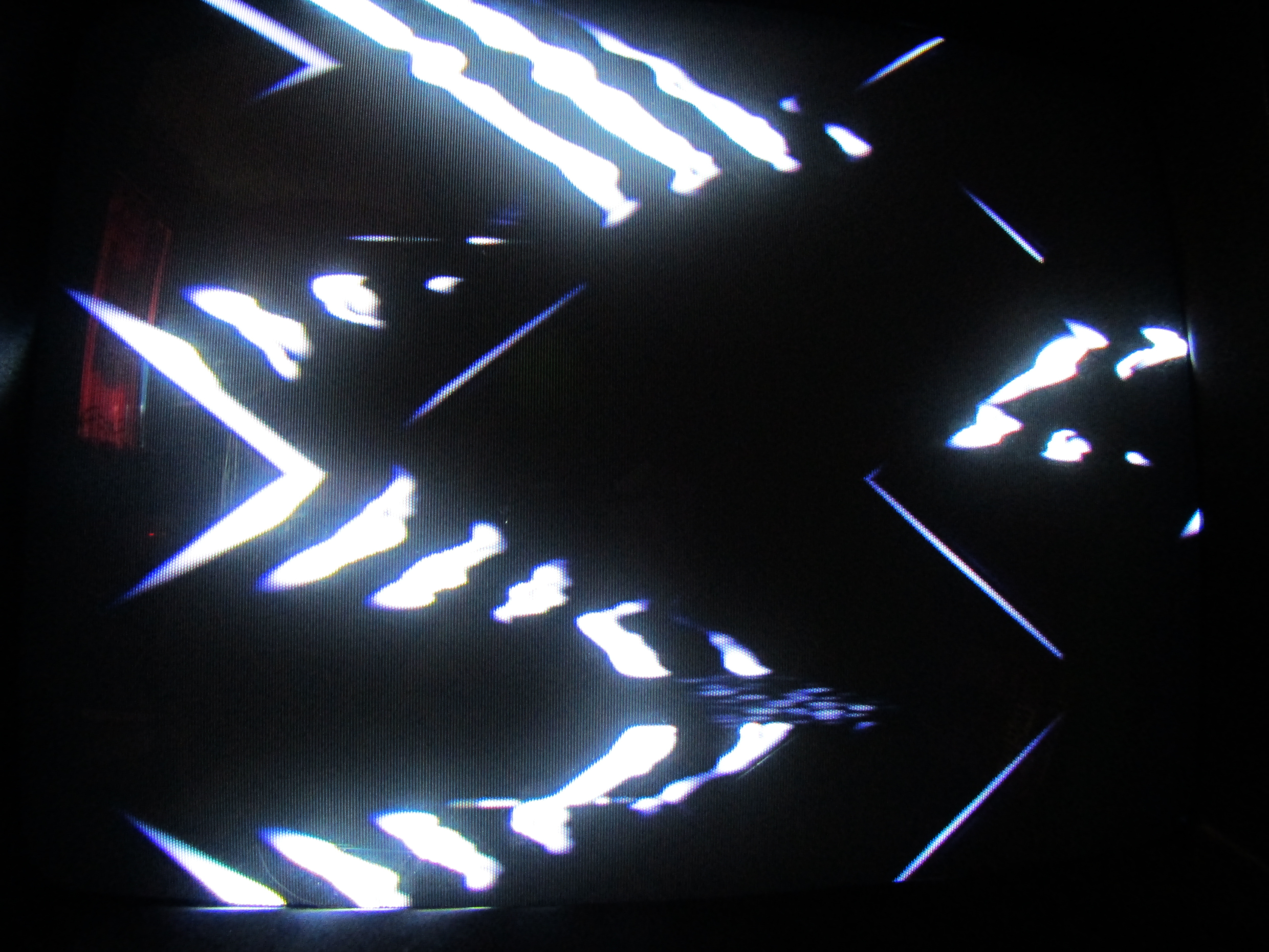
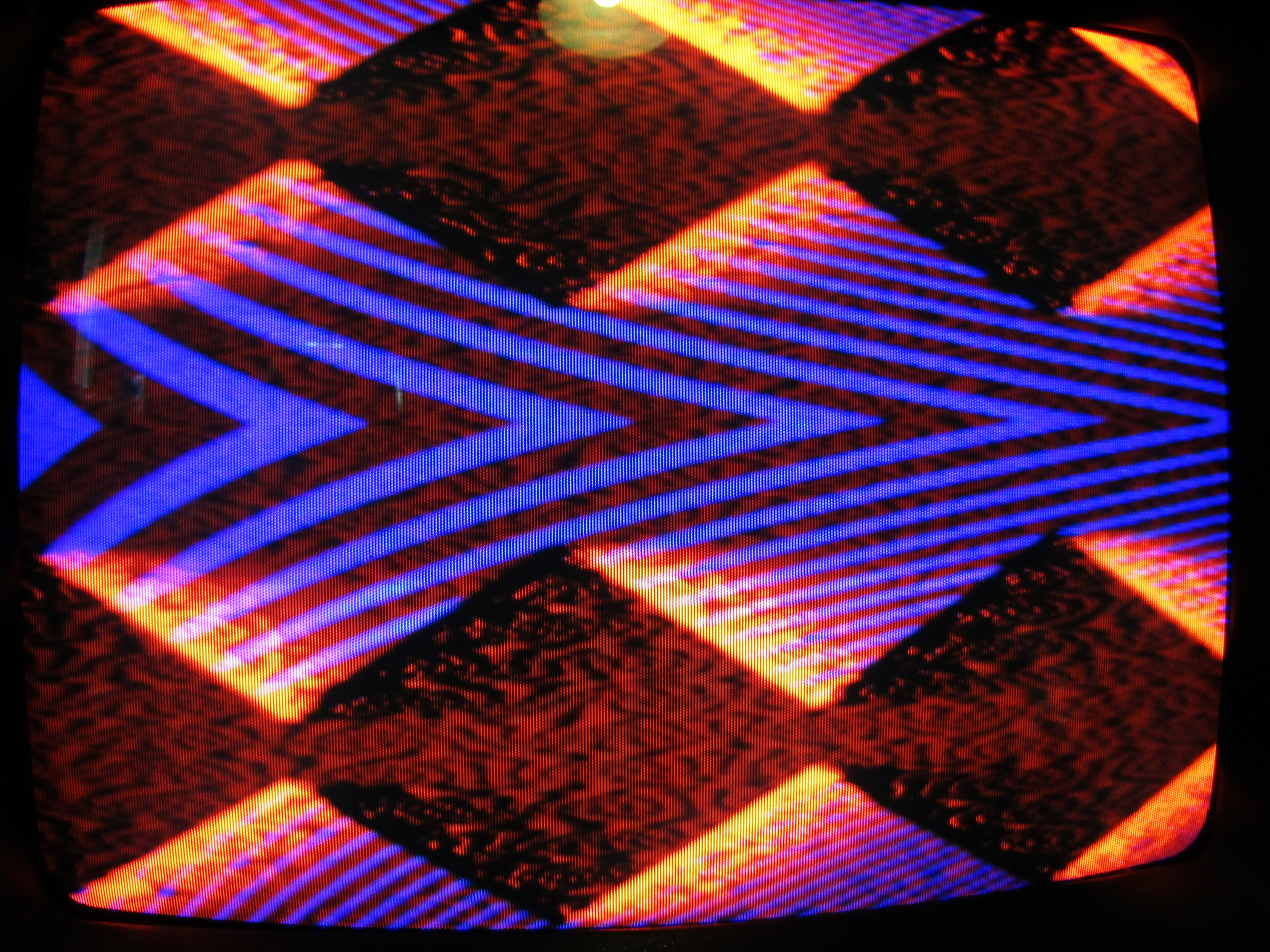
example of feedback edges: (in a patch, no cv yet)
The white dots = edge of the green shape routed though a Differentiator and feedbacked with a modified summing mixer.
(red & blue channel = camera feedback)
Remark: this project is directed towards DIYers and will be open source.
—>> All input and help is welcome!
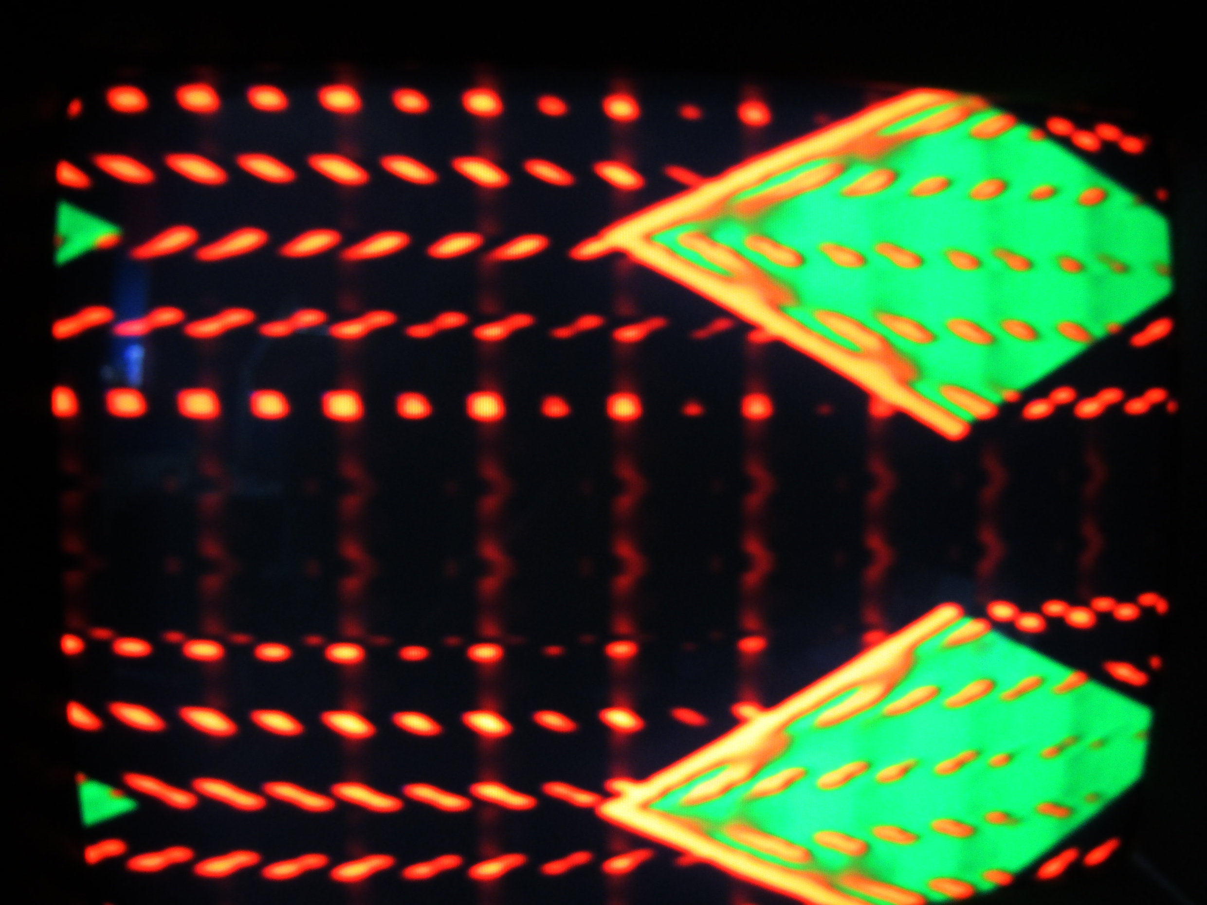
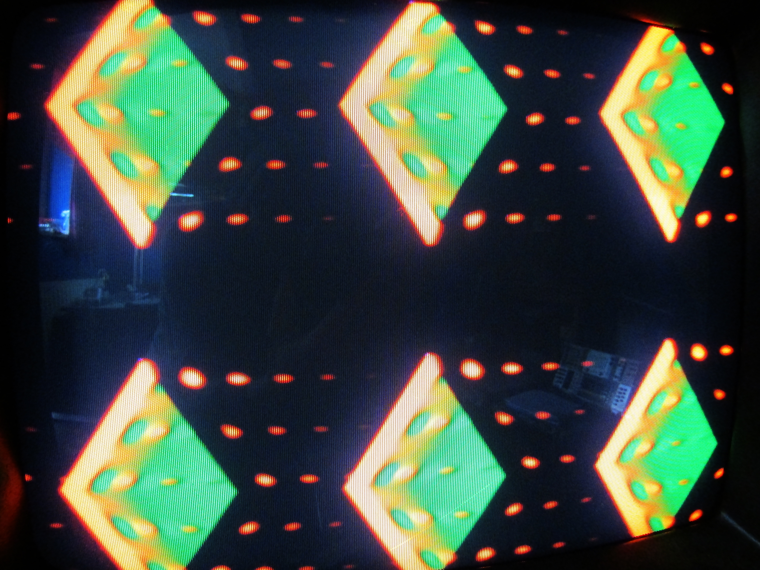
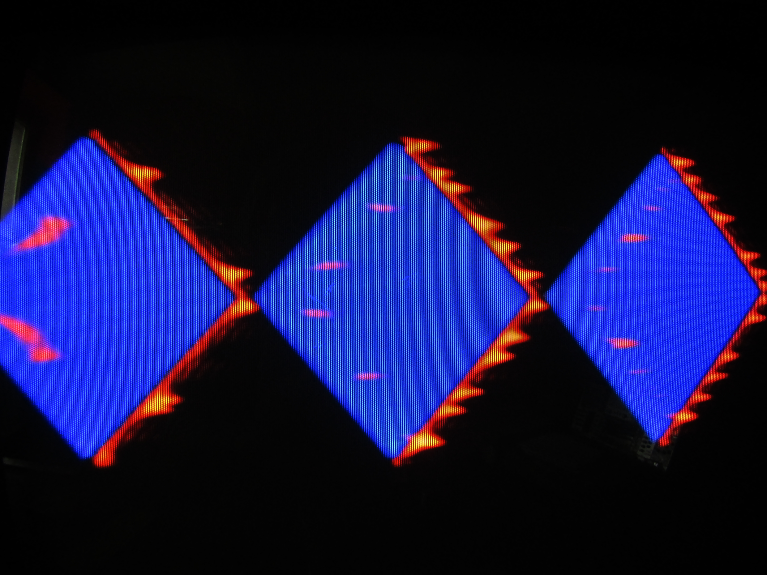
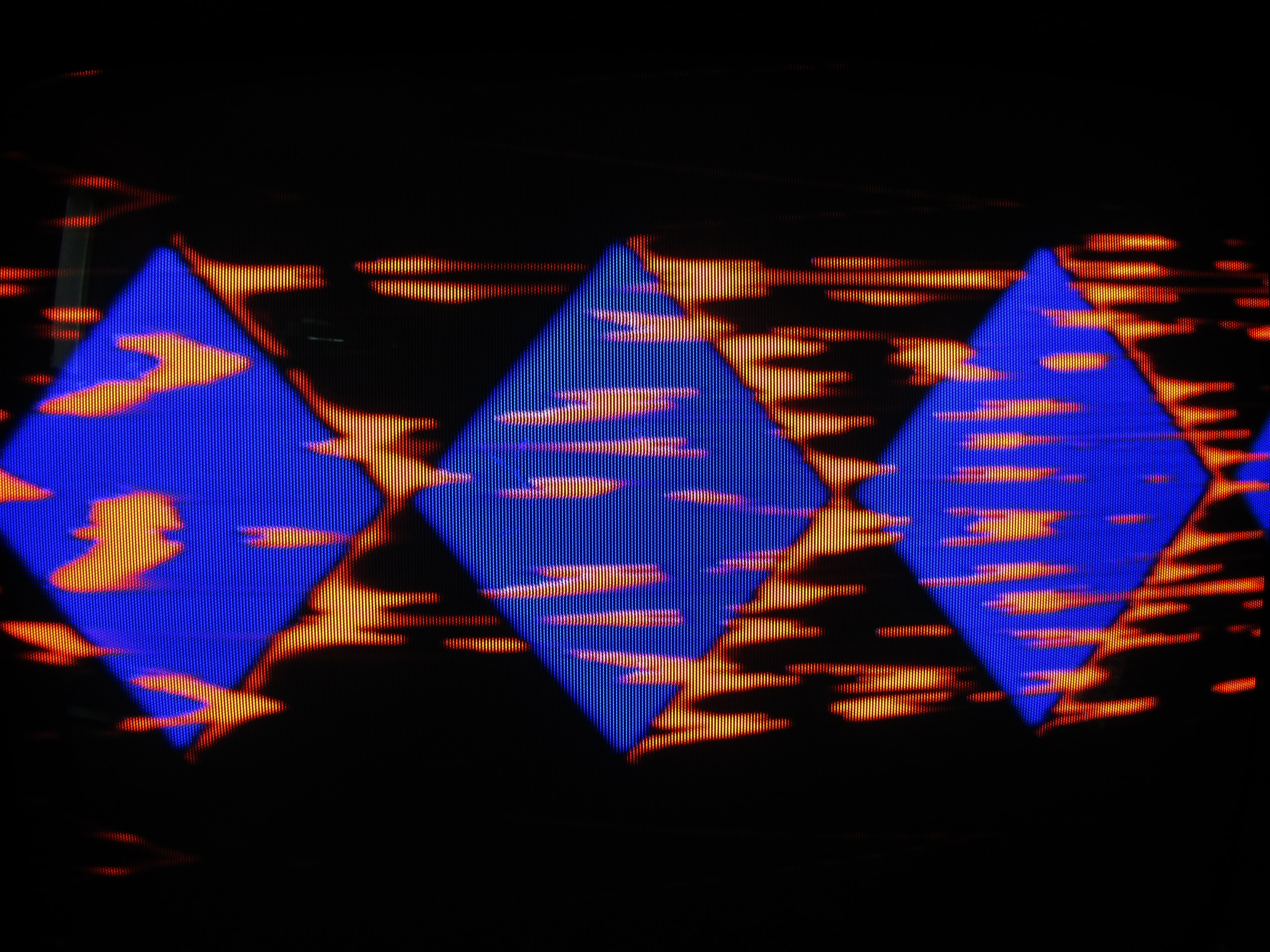
testing with separate modules. fast screensots
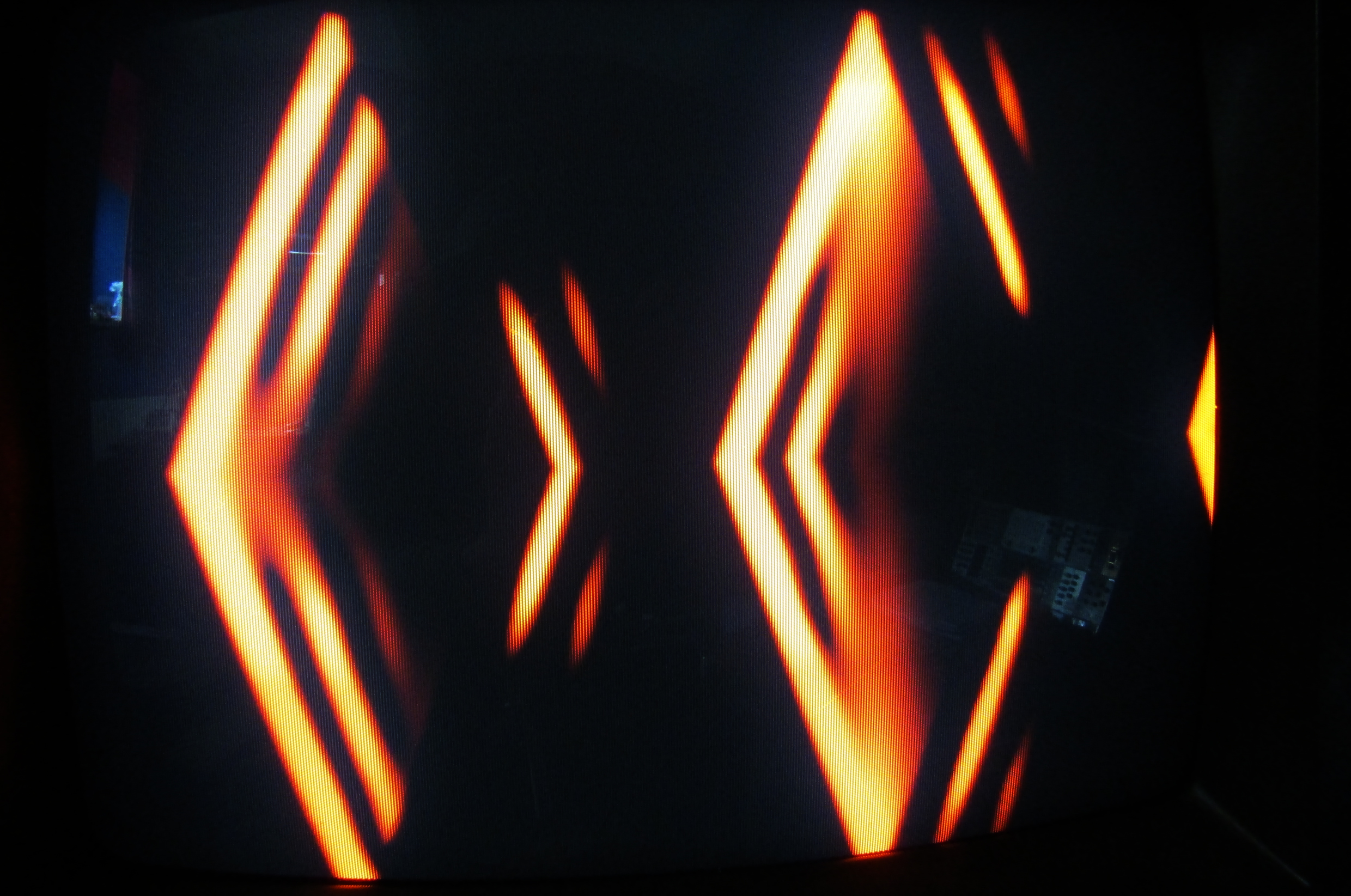
The dots appear when the CV is modulated with a VCO.
The signal needs some boosting to get the repeats, so I have to add this in the schematic (or change some values / make a gain control
The feedback path routing adds nice features, so must be implemented on the front panel; with a rotary encoder or multiple positions switch (4x1)
When several inputs are used, the image get more interesting details (picture 2)
a 100k pot (VR3) in the amp stage of the differentiator works pretty good.
it needs a range limiter (r38) for the low end, which value I have to determine yet.
The Chaos tipping point is tricky. but will be solvable with the right resistors.
I’m getting a lot of cool images already
I wonder if r41 & r42 (or r6) can be skipped. they were final outputs, but not anymore
the same with r44, r47, r45, r46.
this module seems like a neat furthering of that concept. I’m always up for more feedback I’ll happily be following along but have no technical knowledge to lend
Looks great! As far as skipping some parts, I would leave those resistors there to provide some isaolation from the contacts of the mechanical switches. (Are you using a rotary switch here?)
Only sort of half understanding what all is going on here, admittedly, but I wonder if there is a way to introduce variable time/delay to the feedback path for thicker & thinner edge feedback effects (if edge feedback is indeed what is happening here)?
@reverselandfill R3 keeps the input of U3A from floating while the switch is momentarily in a no contact state (which will prevent ringing or other problems you want to avoid.)
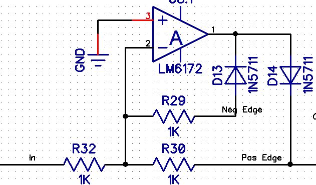
R7 and R8 should be ferrite beads and not resistors.
It would be ideal if the switches were replaced by analog multiplexer (74hc4053, etc) but then you need to add a +5V power supply and some input protection to the lines. For a DIY design I would not worry about it. For a production design, it’d be worth the fix.
What is the intention of the SW and SW2 pads and the switch S1? My suggestion would be to turn the LT1251 into a 4 quadrant multiplier – basically crossfade between the inverted and non-inverted signals. U3A and U4B could be eliminated, as you would send the differentiator buffer amp (U4A) to the non-inverting input on one half of the LT1251 and to the inverting input on the other half of LT1251 in parallel.
If you are looking for more ideas for functions, one would be to use a rectifier to split the positive and negative sides of the differentiator output and make them selectable (left edge only, right edge only, etc.)
sw1 & sw2 : switch pads for the 2quadrant / 4 quadrant mode
S1: switch between positive and negative edges feedback routing
SV2: 4x1 position switch location / rotary
all these will be changed into vertical switches when I decide what to do exactly
note: the 2 & 4 quadrant feedback routing has very different results. maybe it would be interesting to have a gate controlling this. with a 4066 / 4053 or 74HC equivalent. maybe
for feedback options, it is important that the loop gain can be controlled by a CV signal, as it is wired up now.
The test setup gives very good results, so I want to go in that direction.
small schematic update:
pos & neg outputs, for use with the S1/S2 DPDT on/off/on switch, so you cound bypass the feedback path and use the Differentiator “normally”.
2 quadrant in this case is going to be the same as modulating only the top half in 4 quadrant mode: In 2 quadrant mode, you go 0 to 100%. In 4 quadrant mode, you go -100% to +100%. Of course, it is up to you, if you like having the switch. Just saying you don’t lose any features if you remove that switch and just use the 4 quadrant setting (since the inputs are hard tied in this case.) Finding a zero position is more difficult in this case but I think your bypass switch is the superior solution for that issue.
As far as gain goes, you could also add some gain to the LT1251 if you wanted!
For the rectifier circuit, borrow it from the dual clippers in Cadet 2! Like so:
(note you would want to buffer these nets before sending them to the output jack)