I’m still not sure which route I will take.
The x-fade option sounds good, but I hope it will give nice / te same kind of interesting results I had with the things I tried (see above). cq, the amount of feedback
Maybe it will need a polarising pot, to set the zero point of modulation.
I’d be super interested in helping to test. I’m a very experienced DIYer and have ~15 years experience testing software (and obviously the DIY projects i’ve put together).
First order of business is to design the project.
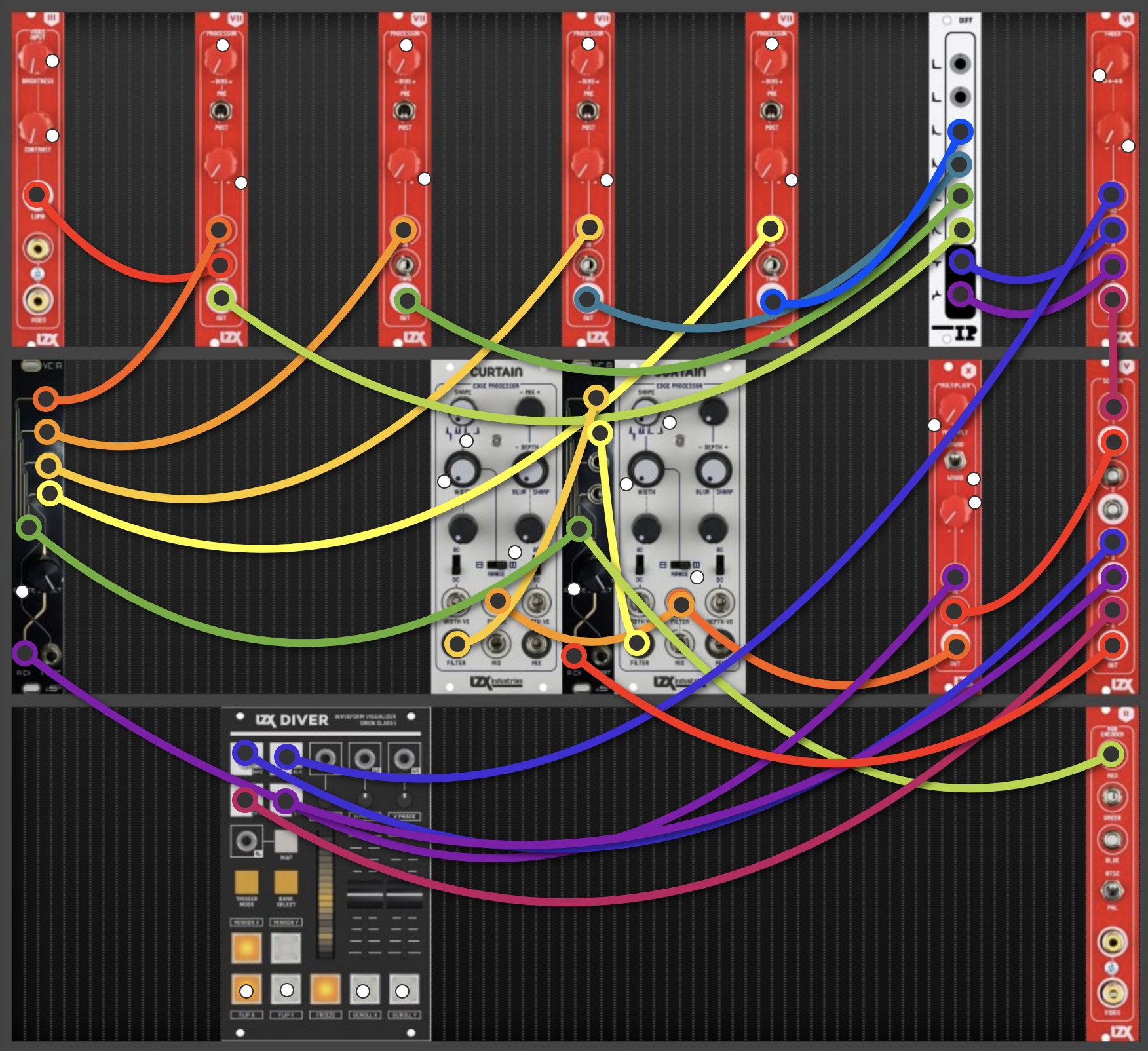
When the prototype is ready, it would be good to test different system routings.
I’d like to make this module because I like to have this effect without having to patch this all the time.
It is a pretty extensive patch, so it would be useful to have a pre-routed module for this (with some added features)
As before, this is an open source project mainly focused on DIY.
My current idea is to have a module that does voltage controlled feedbacked edge re-iterations (see above patch examples)
The possible options are:
switchable edge size (voltage control or by manual switch / patchbay)
triple functions (like my other designs) - mighty be feasible if the panel gets wider
4 quadrant modulation depth vs switchable mode from 2 to 4.
The original LZX Differentiator had 6 inputs (edge thickness/slopes) and 2 outputs (left and right edges)
My 1st design idea had a rotary for 4 inputs (really just 1, but selectable edge thickness) and 2 output (maybe 4 for additional feedback routings
@creatorlars hinted at a variable positive and negative edge outputs (or by CV) . Which sounds like a good plan! The feedback path could be switchable by cv . I have to try if the rate of a CD4066 is fast enough.
Hello,
This sounds really great!
I’ve been playing with the IP Differentiator I got from here a while ago
I’d be happy to help with testing, your ideas for additional functionality look really interesting - building/DIY isn’t a problem (currently ordering bits for the triple Function Gen boards & panel I bought off you).
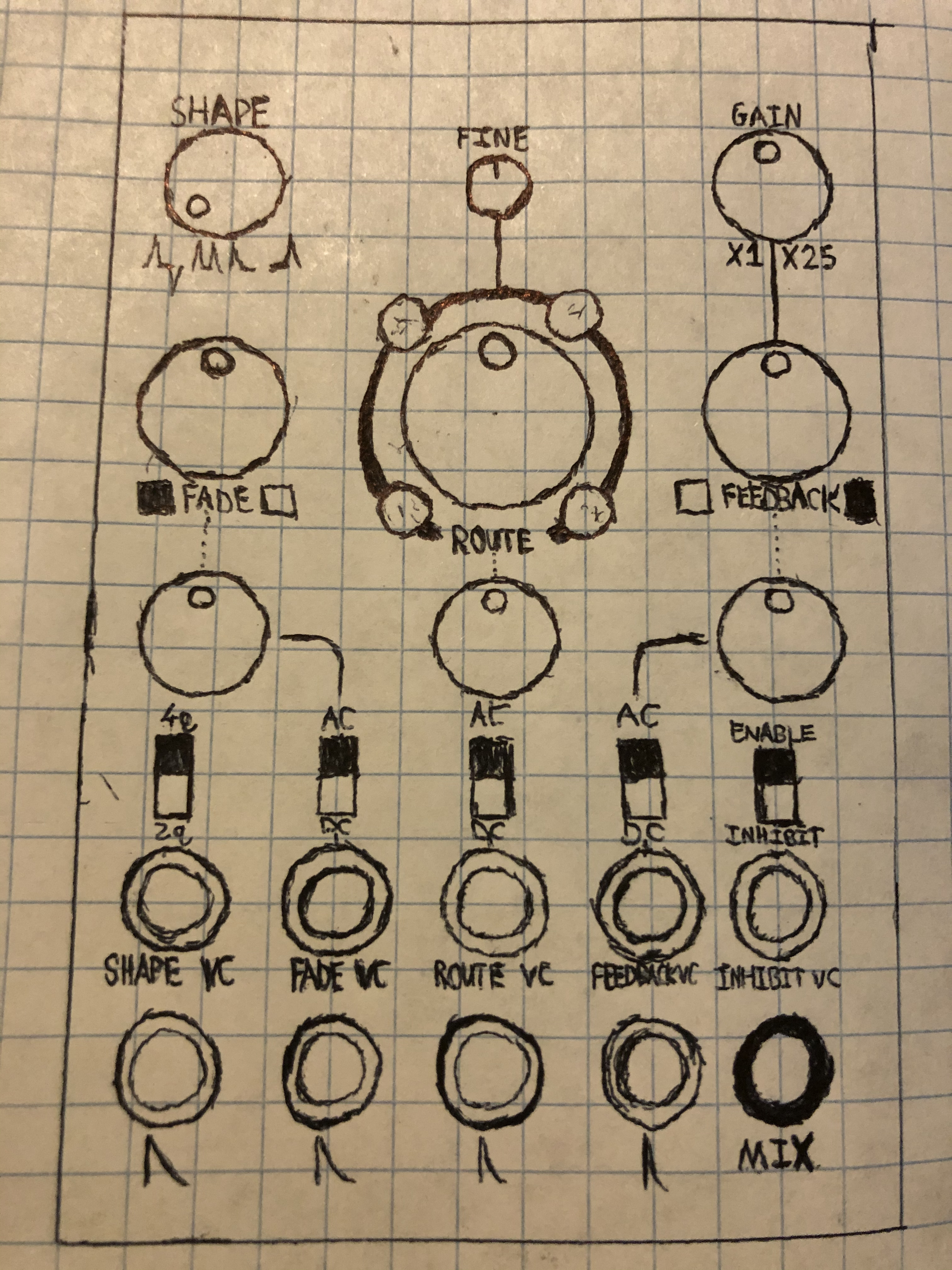
I’ve mulled over some variations on this patch and breadboarded up a good chunk of this circuit to test it out. Something along the lines of the Expedition design layout seemed to fit with the overall feature set this module could have so I did a quick rip off sketch of Navigator:
The module can still work as a standard Differentiator with 4 inputs and a manual fade over non-inverted and inverted outputs instead of the original. Just flip right toggle to Inhibit.
The Route control (w/ Fine adjust) selects which of the Differentiator inputs are tied to the Feedback output control. The Route pot is an offset which adds to the Route VC input. This tracks low detail external Luma video pretty well when I replaced the TL074 CV input buffer + offset mixer with LM6172s.
The Gain control (been using 5x gain so far with a 1->5V Scaler) feeds into the Feedback control which is a 4 quadrant multiplier switchable to 2q/VCA. This is fed into the Route control’s internal input. The 4 outputs of the Route circuitry are mixed unity gain into the Differentiator’s 4 inputs.
The Fade control is a Cadet Fader that takes the non-inverted and inverted outputs of the Differentiator and feeds the output into the Shape control.
The Shape pot is the same idea as the one in Curtain (different offset/mixes of the Cadet II clipper circuit, I think) but you can scan through the rectifications with a second voltage controlled router, Shape VC. Shape pot adds an offset to the Shape VC input.
The Enable / Inhibit toggle is a bypass for the feedback path that’s just disabling the DG409’s I/O. The Inhibit VC input can be modulated up to very high audio rate and creates some of the horizontal smears in the clips.
I’m currently working on getting the rest of the circuits up on the breadboard to confirm functionality but would be interested in any feedback!
wow! this looks really good - I love the way the feedback looks
I have been making similar effects with some Castle+Cadet+one Differentiator+Matrix Mixer (don’t ask me for the patch tho… it’s all changed since)
Anyway, count me IN - hopefully there could be a DIY version… at some point
Thanks, I’ve been using variations on this patch a lot recently and video rate filter bank feedback gets my vote! I’m not quite onto the board layout stage yet but it’s likely this will require a SMT design (0805/SOIC ideally) so it’s not ridiculously deep at 16HP.
I’d like to offer bare PCBs at the least but plenty of work to do before we get there!
I started working on this project again. I just want to make a simple version first, then we will see if it can be a larger module too.
Current featureset:
3 filter inputs, 2 of which can be the the feedback path (with a switch)
CV over feedback amount
Level pot, Feedback pot, Filter gain pot, CV amount pot
pos/neg signal switch
Note: this is a prototype, so some of the controls are experiments
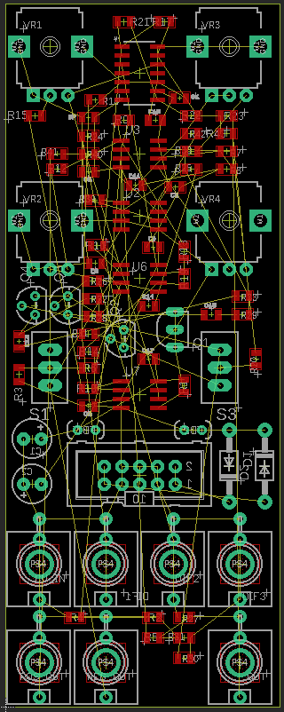
here is my current layout, my first SMT . I have to find certain parts in that format, so that is why the transistors are still TH. I think I will keep the power parts TH (on the backside), the rest of the SMT is on top. The size format is 0805.
Just caught up on the thread now - looks great! I have two differentiators in my system and have always thought it would be nice to have some internal control on the feedback to simplify patching, good to know others are on a similar wavelength.
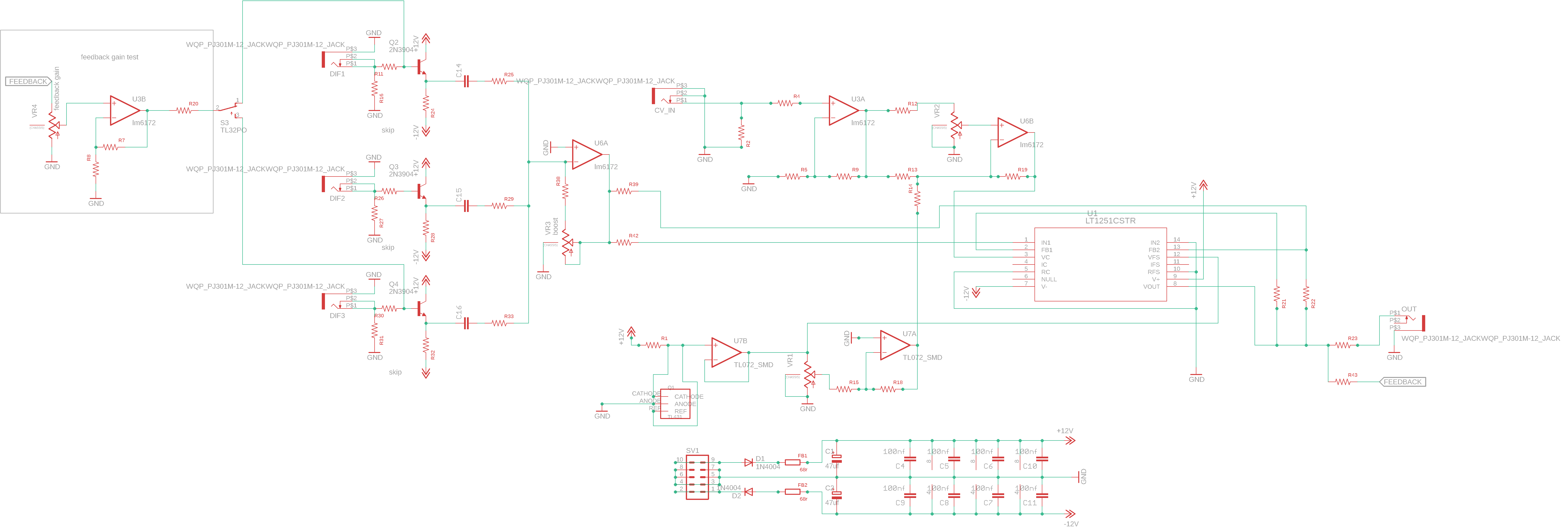
I’m trying to implement @creatorlars idea from above, which was to lose one LM6172 and crossfade between the negative and positive outputs of the filter.
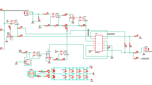
So this is what I got now. Maybe somebody can check if I made errors somewhere?
the feedback gain area is a test. I have to add all resistor & capacitor values since I converted the parts to SMT.
now that I look at it again, my schematic looks wrong. I misread the suggestion a bit
Let’s see if I can setup the lt1251 as described. I’m wondering how to make sure the inverting amp stage is connected correctly to the output pin with resistors…
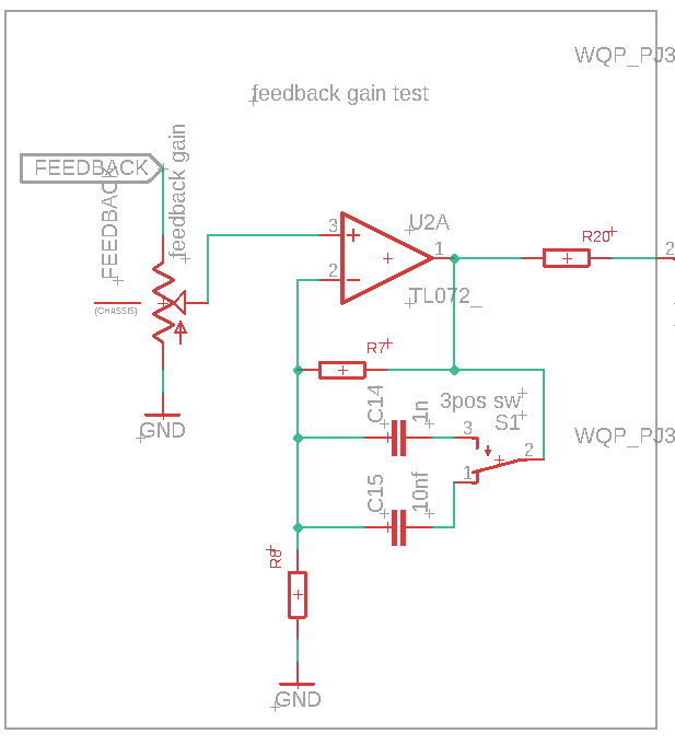
I did a simulation , I added a switchable cap at the feedback path. I think this will give nice smoothing to the feedbacked edges. The part values are chosen to make it visually clear (not video freq), but it should work similarly .
schematic with switchable smoothing (3 pos switch, on-off-on)