Hi!
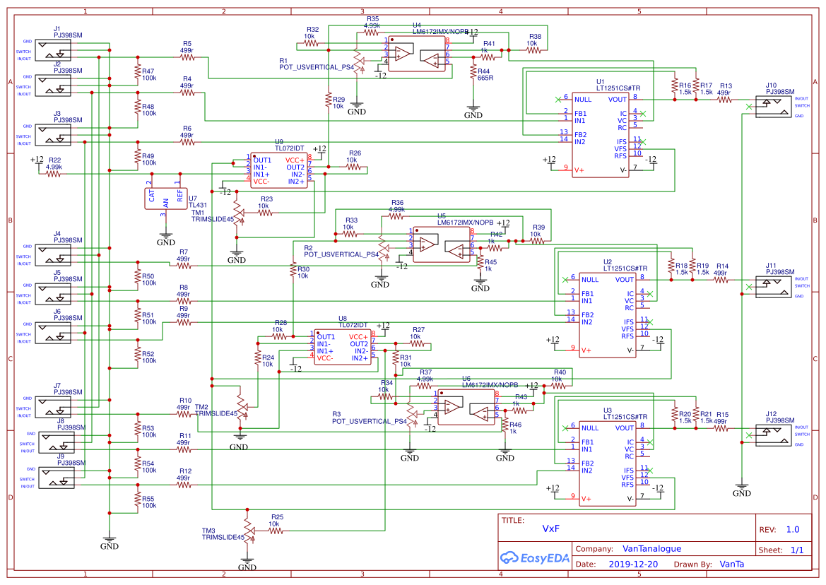
Just wanted to share an idea. It’s basically 3xCadet VI faders smashed together with Slider Potentiometers and Normaled inputs. I’d like to be able to crossfade between two 2RGB signals.
I don’t expect anybody to go through the schematics (it’s the first time I draw one, and its a bit chaotic).
But I would appreciate any tips on sandwiching? It’s probably going to be a 10HP sandwich design with smt components DIY friendly.
I’ll try to order a test pcb over christmas and start the new year with this new exciting project ![]()
Wish me luck.
9 Likes
Something like this for the interface:
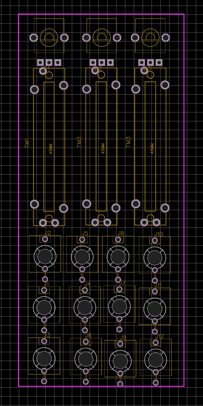
First three columns of thonkiconns are In-A, xFade, In-B , the last column is out RGB.
4 Likes
did you add capacitors around the powerheader (10uF electrolythics) and 100nF capacitors next to the IC’s? I don’t see them on the schematic. Look at Cadet schematics for examples on this.
3 Likes
True! the power section is not there yet. Thanks!
1 Like
Nice!! I want one… my recommendation make the INPUT normalizations cascade (similar to Passage) that will be the most flexible o all combinations :), including both A/B inputs and CV. Also dont be afraid of doing it SMD 0805 is big enough and ICs are ez to solder even the inexperienced.
A1 > A2 > A3
B1 > B2 > B3
CV1 > CV2 > CV3
3 Likes
I use my current 3x Faders for this task and this layout looks ideal. Agree with normalizing inputs, it makes patching way less messy. Hope you can turn this into a DIY project for the community!
2 Likes
Cool, thanks!
Normalized inputs are already in the schematics, I think that part is correct.
Should I buffer the first inputs because of the cascading? Or is it ok like in the original cadet circuit?
The idea of this project is threefold: give back something to the community, enrich the video DIY universe and learn the process of creating a module. That’s why I chose this ‘easy’ design. I have more ideas, but let’s test this one first. ![]()
1 Like
What about adding a flipflop to each fader? So you can switch A<=>B with triggers for animation…
I would LOVE to have a fader with either some flipflops or a simple AD. Thats basically a LZX Pendulum but with triggers input.
4 Likes
Thats very interesting.
An analog switch would do the trick, maybe this: https://www.maximintegrated.com/en/products/analog/analog-switches-multiplexers/MAX4760.html
Didn’t really check the bandwidth and other specs, but some chip in that direction.
That will change the layout, though. I didn’t want to go bigger than 8hp…
But if the analog switch is fast enough, it could even work as a threshold.
1 Like
I’d be interested in one of these. It looks really handy.
1 Like
This looks super cool. I would be interested as well if you did a run of them.
1 Like
Hey @VanTa 
How is your cross fader project coming along? I never read the thread until now but this sounds great. If this worked, could you please share some photos of its visual output & also the finished model & PCB. I’m really curious 
note on board connectors:
I have done a few experiments with pin headers. For bigger pcb’s: if you use (for example) 2x 1x6 headers on both sides of the ‘main’ pcb and a 2x4 on top / bottom, it makes a firm connection (so you don’t need any standoffs and screws to keep it all in place)
1 Like
Ah, now that you’ve written that I realise that I’ve seen standoffs used on bigger modules or on smaller modules where a single one is used because there’s very little header connections.
Funny that you say about pin headers, I’m planning to use them but in a funny way, more to come 
The project is coming slowly forward, I don’t have much time to put into it sadly. And I’m also not proficient with KiCad yet.
There’s 3 modules on the drawing right now, focused on live performance.
1 Like
I have plenty of time to help when I’m at work, but I use Eagle.
2 Likes
I’m really curious now, headers make perfect jumpers & using them with jumper cables for patching is a great idea when space is absolutely critical. So are you creating a 4x4 or 8x4 header matrix on a front panel?
On the subject of cross-fader modules: I will be offering a PCB/panel set for DIY builders soon, which provides three channel (RGB) cross-fader/keyer functionality between two sets of RGB inputs. I’ll write more soon, but if you’re interested or have questions now then please feel free to PM me!
9 Likes
Wouldn’t this be better on its own thread?
I’m interested and have a number of questions about it, but I wouldn’t want to confuse anybody that is following the VxF vantalogue RGB crossfader project.
1 Like
Sorry, yes, this was rude of me - I have cut my post back. Sometimes I start typing and get carried away 
1 Like