Project description:
I want to make a Triple Function generator based on the Sandin/LZX design.
The function generator is very cool if you use it to re-colorise the B/W Luma input .
Especially with camera feedback, this gives very beautiful results.
Each generator stage can be used individually too.
Features:
- 3x shaper for re-colorizing the B/W Luma video input and other processing
- normalised inputs
Options:
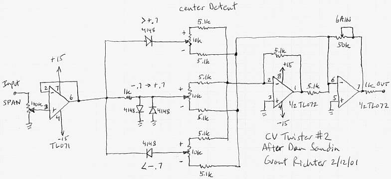
- extra gain & span pots? See Grant Richters adapted schematic below - to be tested
- main pcb + control pcb + panel pcb
- feedback? - to be tested and checked if this is interesting.
- CV control? if this is possible. please help!
Note: this project is directed towards DIYers and is open source.
7 Likes
basic layout , gain to be tested
3 Likes
so I love the function generator too! these are fantastic modules I have an idea though…
how about a single function gen whose three levels are normalled to the inputs of function generators 2-4
input into function gen 1
High band (from function gen 1) out into function gen 2
mid band (from function gen 1) out into function gen 3
low band (from function gen 1) out into function gen 4
I am in no way electronically inclined so I’m not sure if that is how this circuit works at all
I’m following along with this one too
I’ll probe the circuit at some points, let’s see if I can tap certain stages and give them a output.
1 Like
I had an idea:
option 1:
single pcb + a single FG panel
option 2:
3x single pcb + a triple FG panel
I have the layout of this direction done. I just have to make the panel pcb’s
I might add some extra functions, I have to test those first.
For the triple option, I want to have some normalled connections, which can be achieved by interconnecting the pcb’s (the “NORM” pads)
The pcb’s use right angled 9mm pots and are relativly shallow when mounted to the panel. (3.5cm)
ps: if anyone has a footprint of a rightangled dpdt switch, let me know!
2 Likes
look at my Differentiator VC feedback project page.
I want to aim that project more to a “newer” idea. If I also want to make it triple, it will become a very big project that cannot be made easy in TH parts I think (or it will have several pcb’s sandwiched together.)
But I will keep it in mind 
maybe it can be done?
1 Like
I have 3 Funk GenZ and can confirm that the fun factor is high.
1 Like
Indeed 
especially with colorising video input in a feedback setup , amongst other uses
1 Like
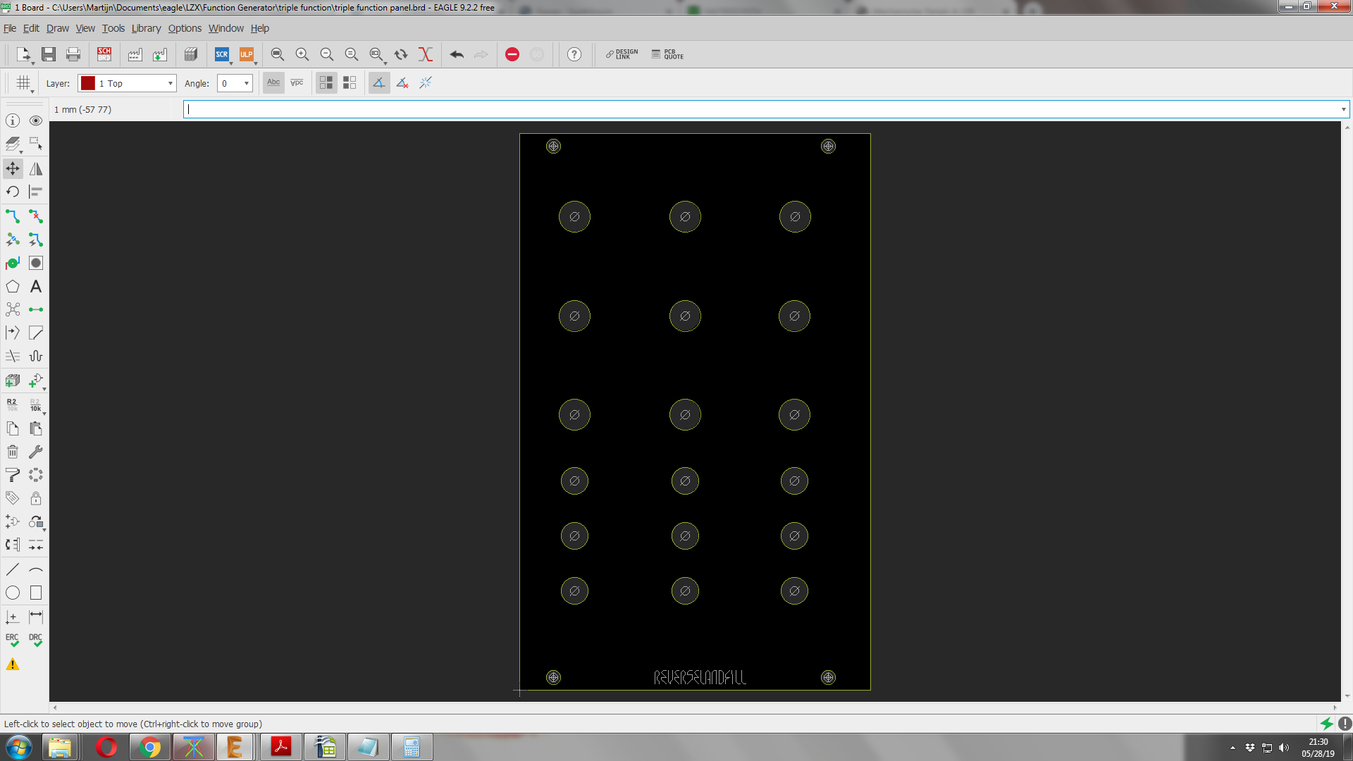
I’m working on the triple panel now. it is 16HP right now.
pot & jack positions will change , because I might add a pot in the design.
(and I have to check if the panels will fit sideways. )
work in progress 
3 Likes
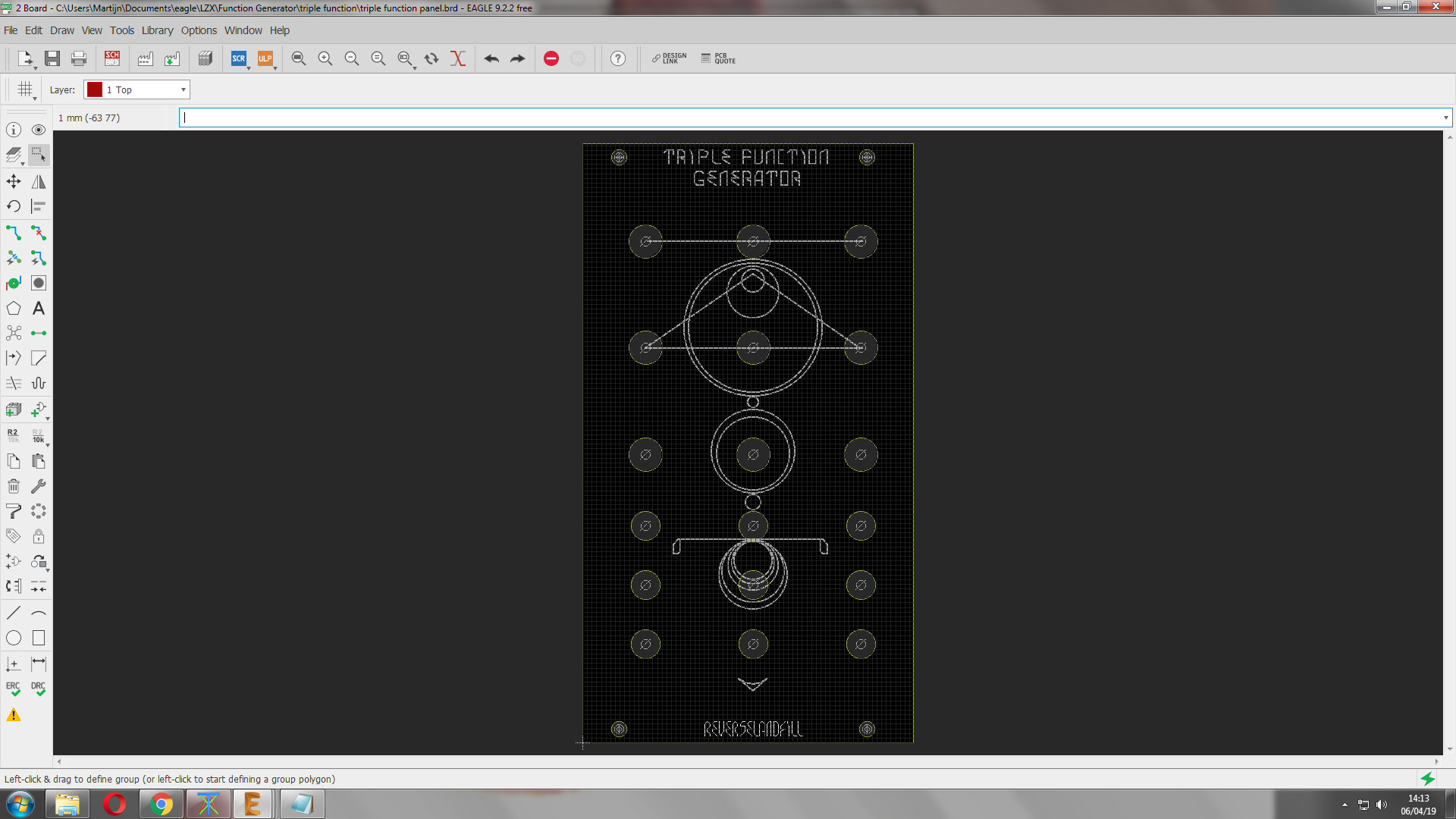
a more final design. (almost)
sideway mounting fits. 14HP
7 Likes
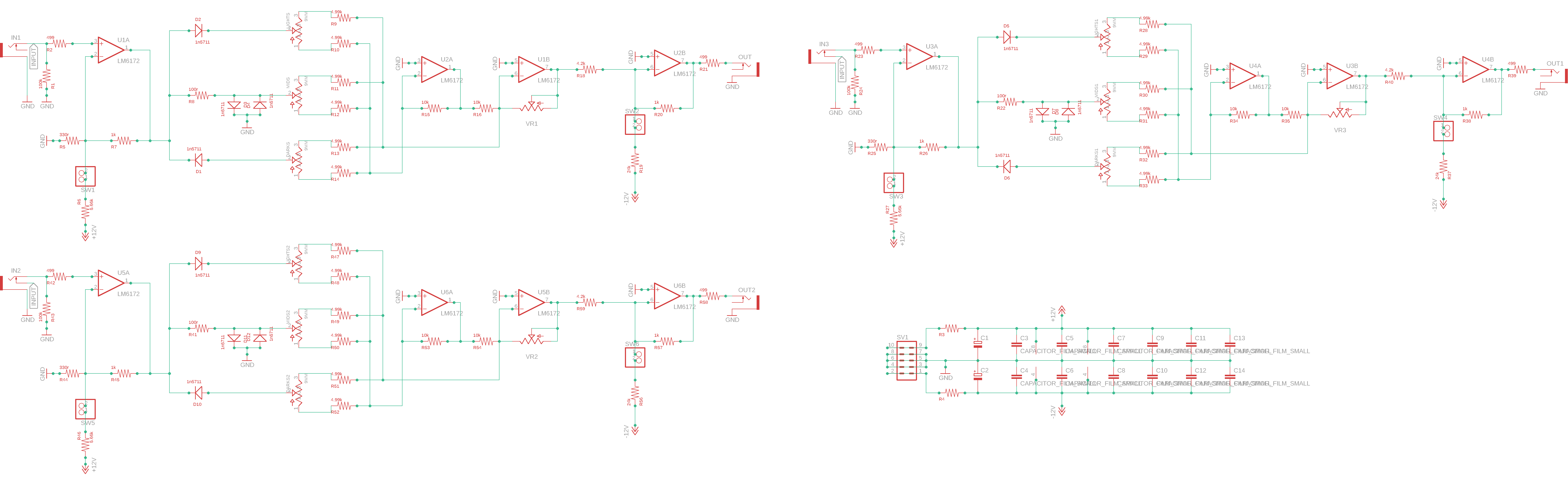
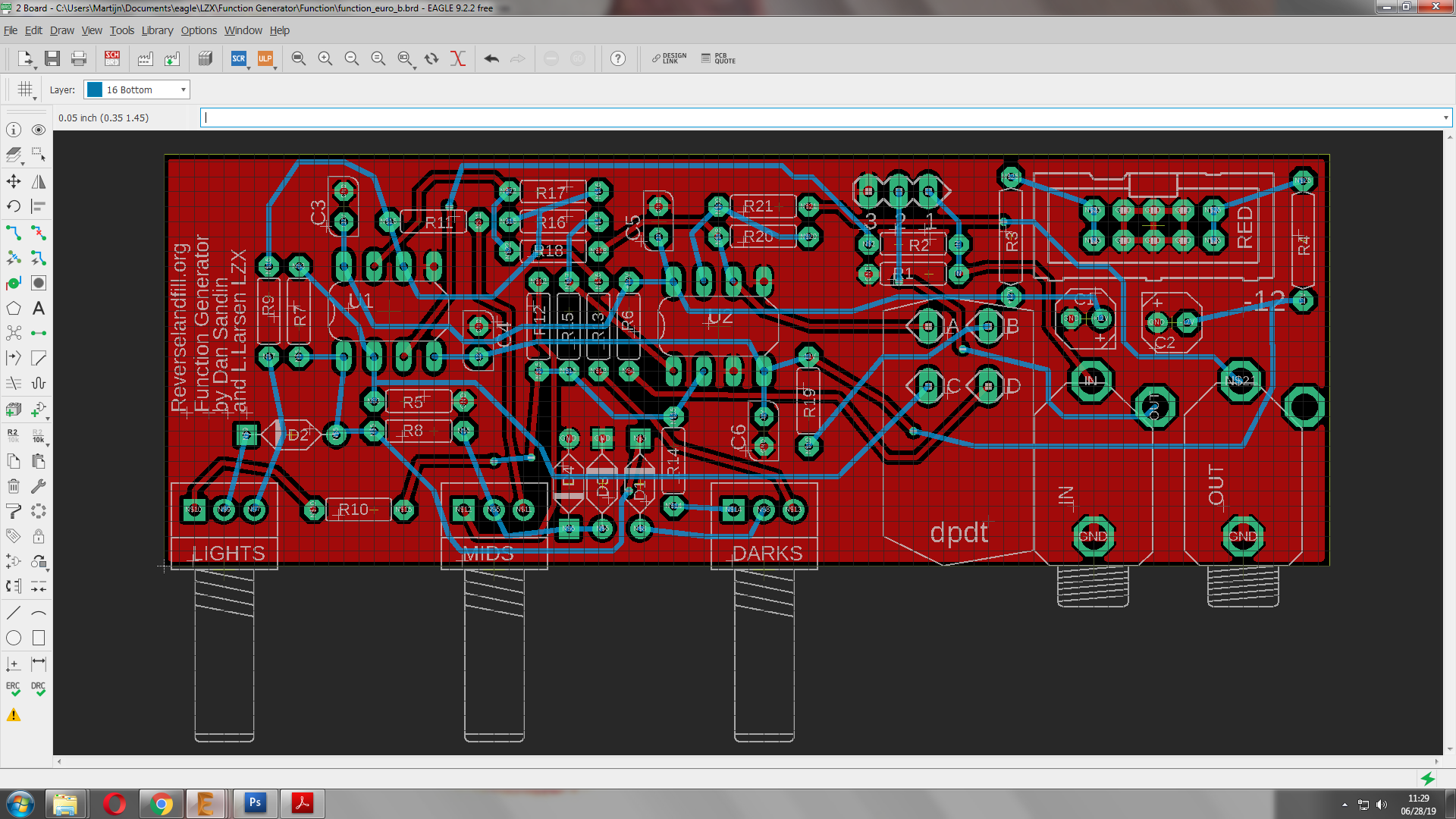
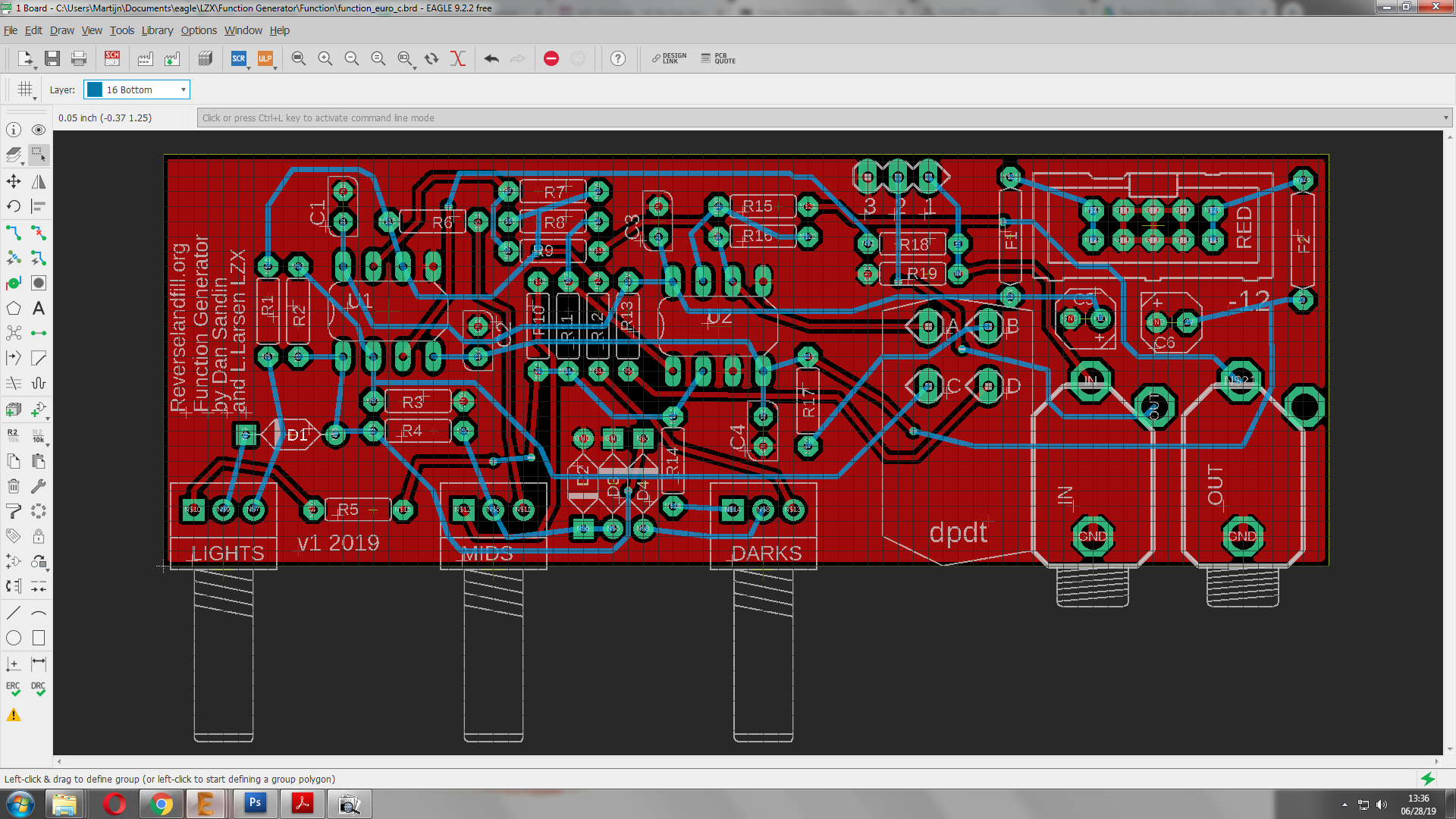
pcb design almost done.
changes:
-connection holes for normalisation
-dpdt pads placement
1 Like
Those bottom layer traces up top are a bit too close to the board edge, and D4 might be closer to the MIDS pot than ideal, but appart from that this is starting to look good.
Would you be adverse to re-annotating the board? I find that it generally makes assembly a lot easier, especially if you’re not too familiar with the design.
the DRC check reported no errors, so I think it is ok.
what do you suggest as for the re-annotating? part values?
Normally I will make a detailled build guide + BOM
I just ordered the pcb’s, so I can still change things
traces and diodes moved.
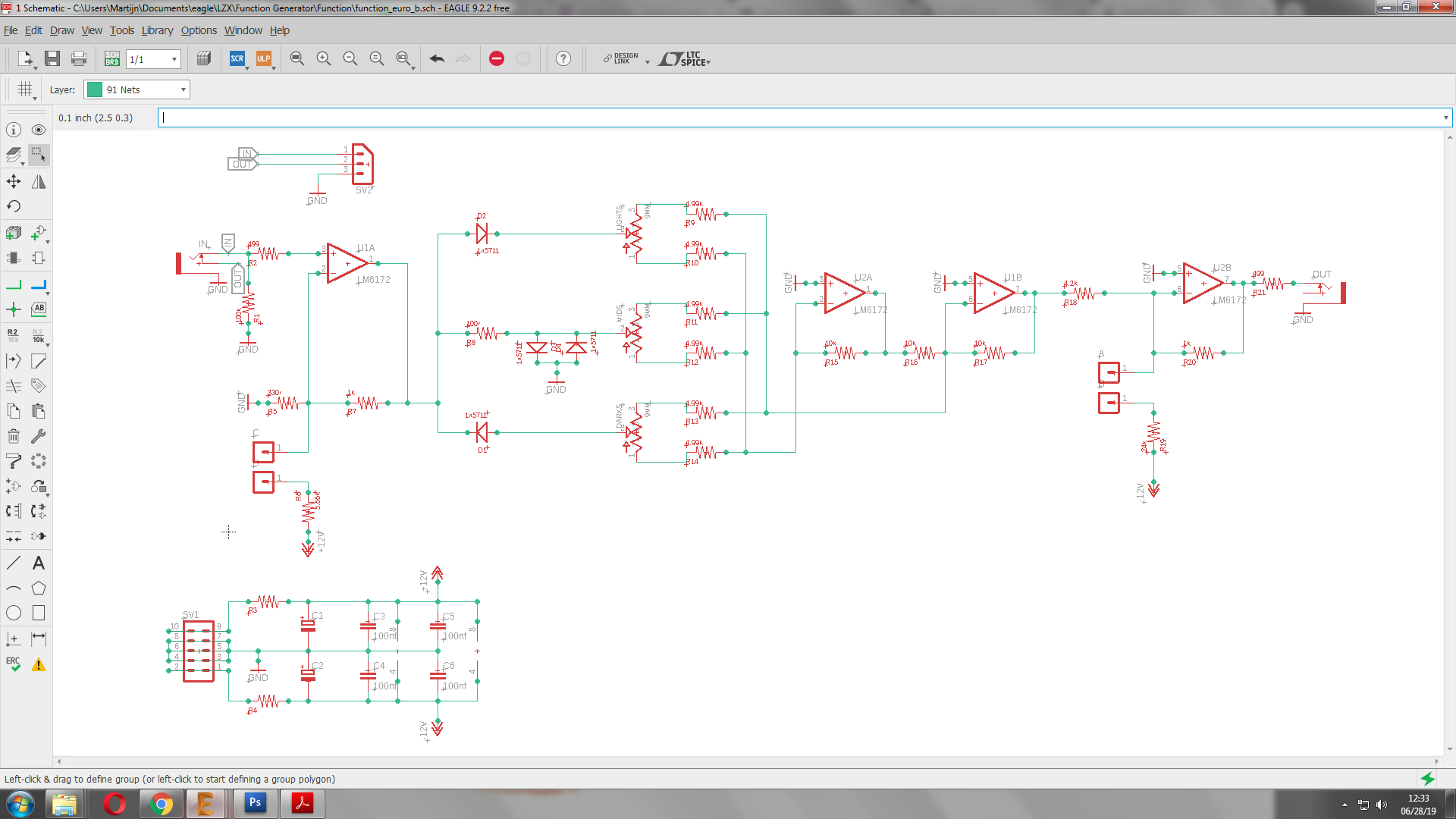
final schematic (for now) - another experimental pcb will be made to explore functions described in the 1st post.
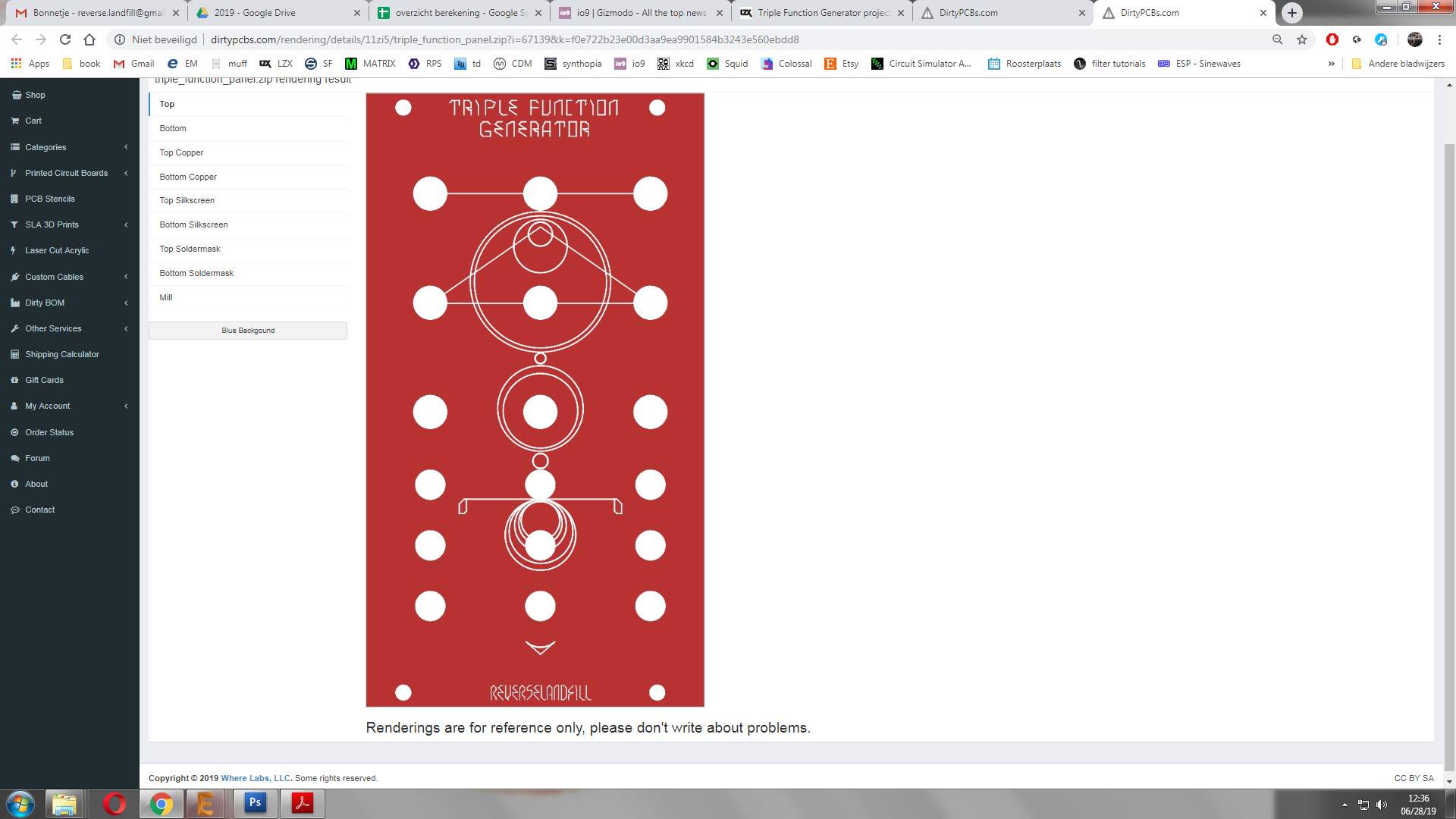
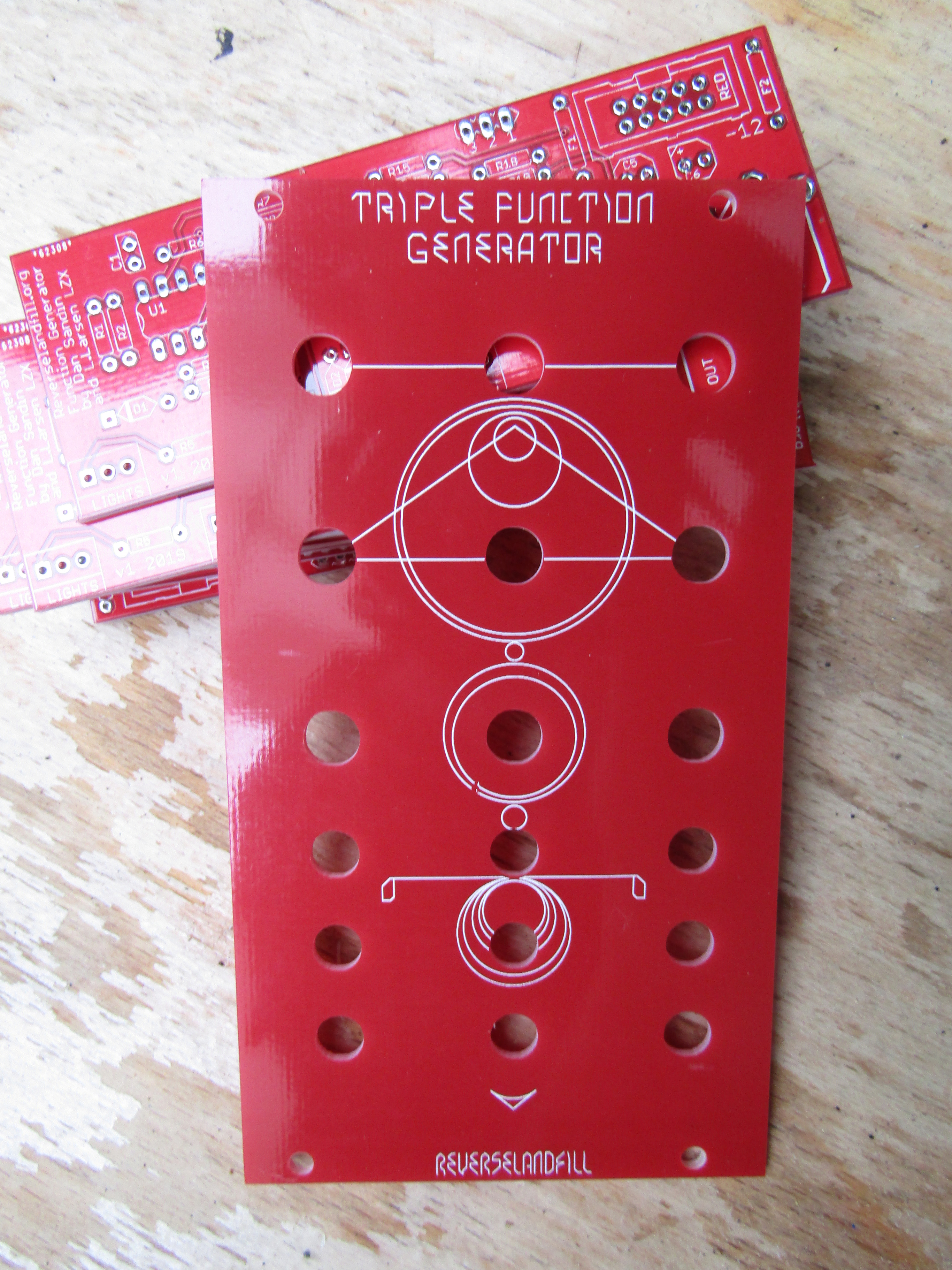
panel look. red!
1 Like
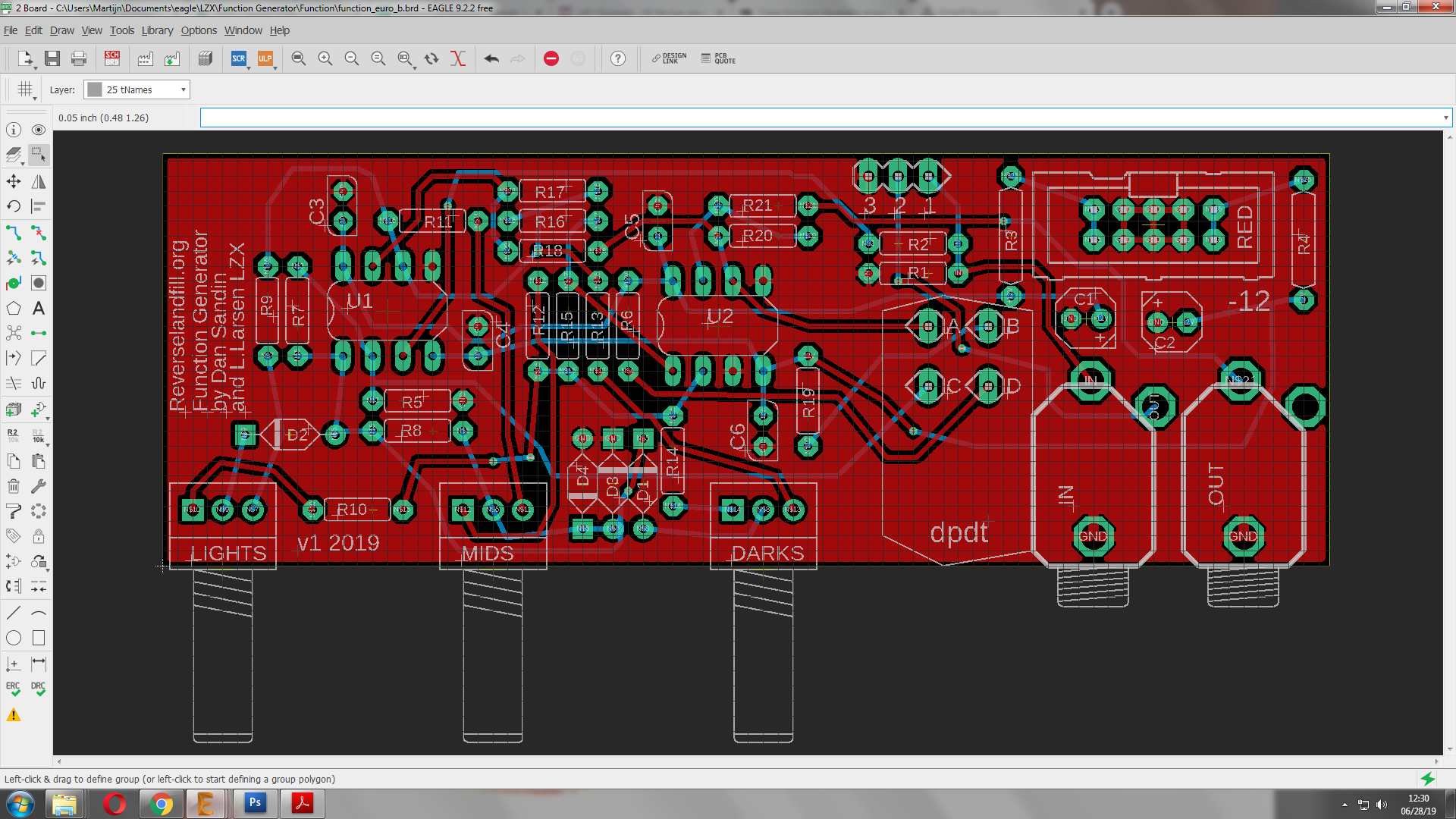
Re-annotation by position, i.e. updating the designators such that they increase along the board.
It’s just one of those small things, so if you’ve already ordered boards i’d just leave it as is.
ah, ok.
I will do that. then it will become less of a puzzle.
and done (manually, because the Eagle ULP sucked)
note:
I just made a cool feedback test patch with 1x function generator + 2x processor.
This gives very interesting results, although it needs much adjustments.
Chaining, as opposed to splitting the input signal, is also very useful.
This can be achieved with the normalisation pads. maybe it is a good idea to make an expansion panel with some switches to change between these routings. I’ll leave that to you DIYers
1 Like
the pcb’s are now on its way to me .. 

5 Likes
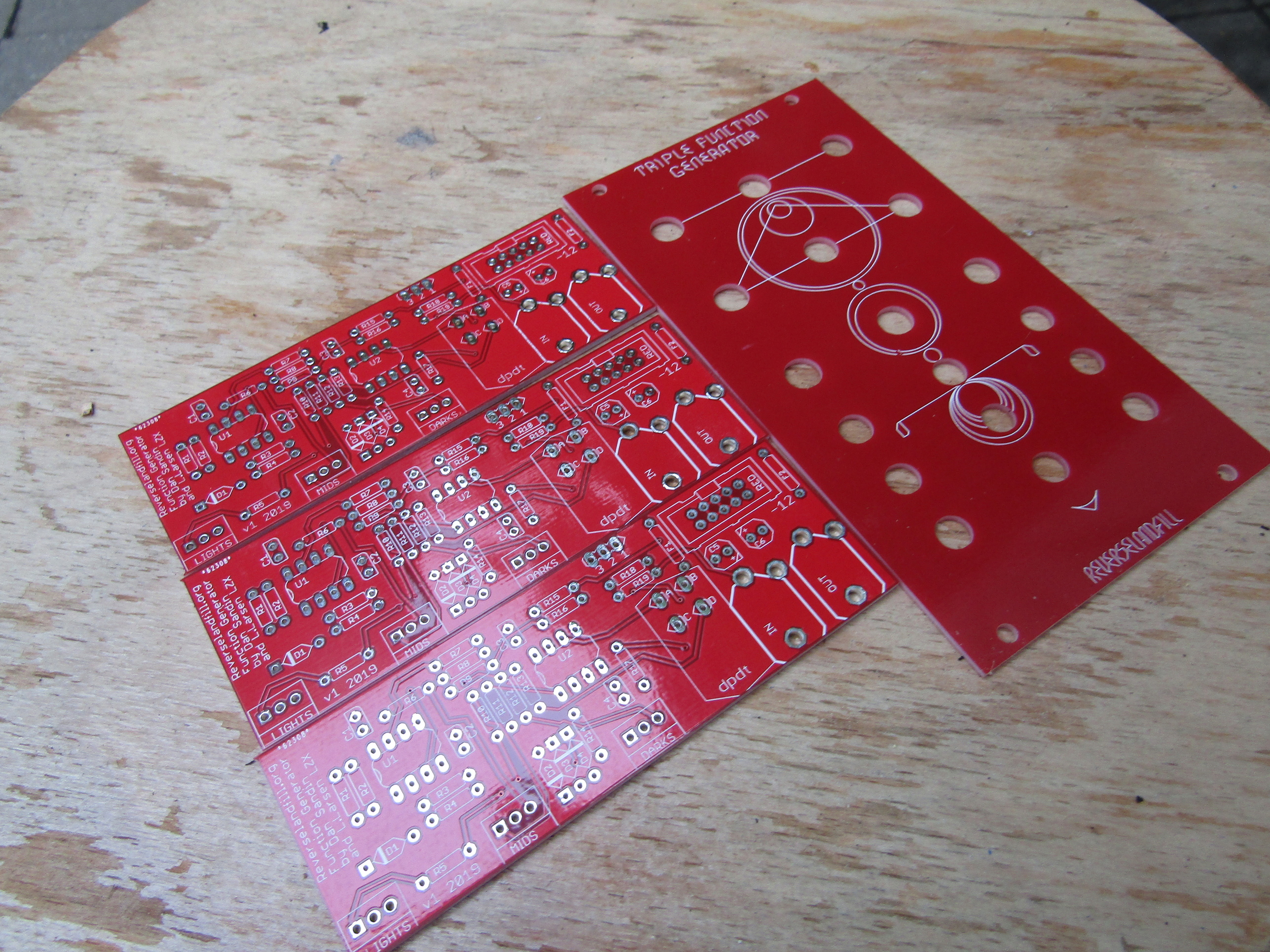
And they are here! The panel looks really cool in red 
I will build one , if it works, I’ll make an ORDER thread!
I have 24 FunctionGenerator pcb’s and 22 panels. you need a set of 3 for each panel so I have 8 sets for now.
you can also make a single one and diy the panel.
We will see how it goes
15 Likes
is this batch going to be for DIYers only?
1 Like