I find myself using a TL431 only if I don’t already have a 7805. There are special, more sensitive cases though. Such as the voltage controlled current source like you can see in the ramp generator or vco.
2 Likes
Ah, yes - you’re quite correct. No need to use a TL431 because of the 7805.
1 Like
Thats just my opinion though and I probably have the noisiest power supply possible! A precision voltage reference would benefit any design if you really need one. I’m not trying to say the opinion is absolute.
2 Likes
Of course, but what you said makes complete sense. The TL431 isn’t usually needed for steady reference voltages rails, since the 7805 is already fulfilling that role. But if there is a requirement for one (like the VCO constant current source you mention) then it can be added on the main veroboard section. It’s about balancing how often something will be needed (in this case not very often) against how much space it will take up to include it on every board.
2 Likes
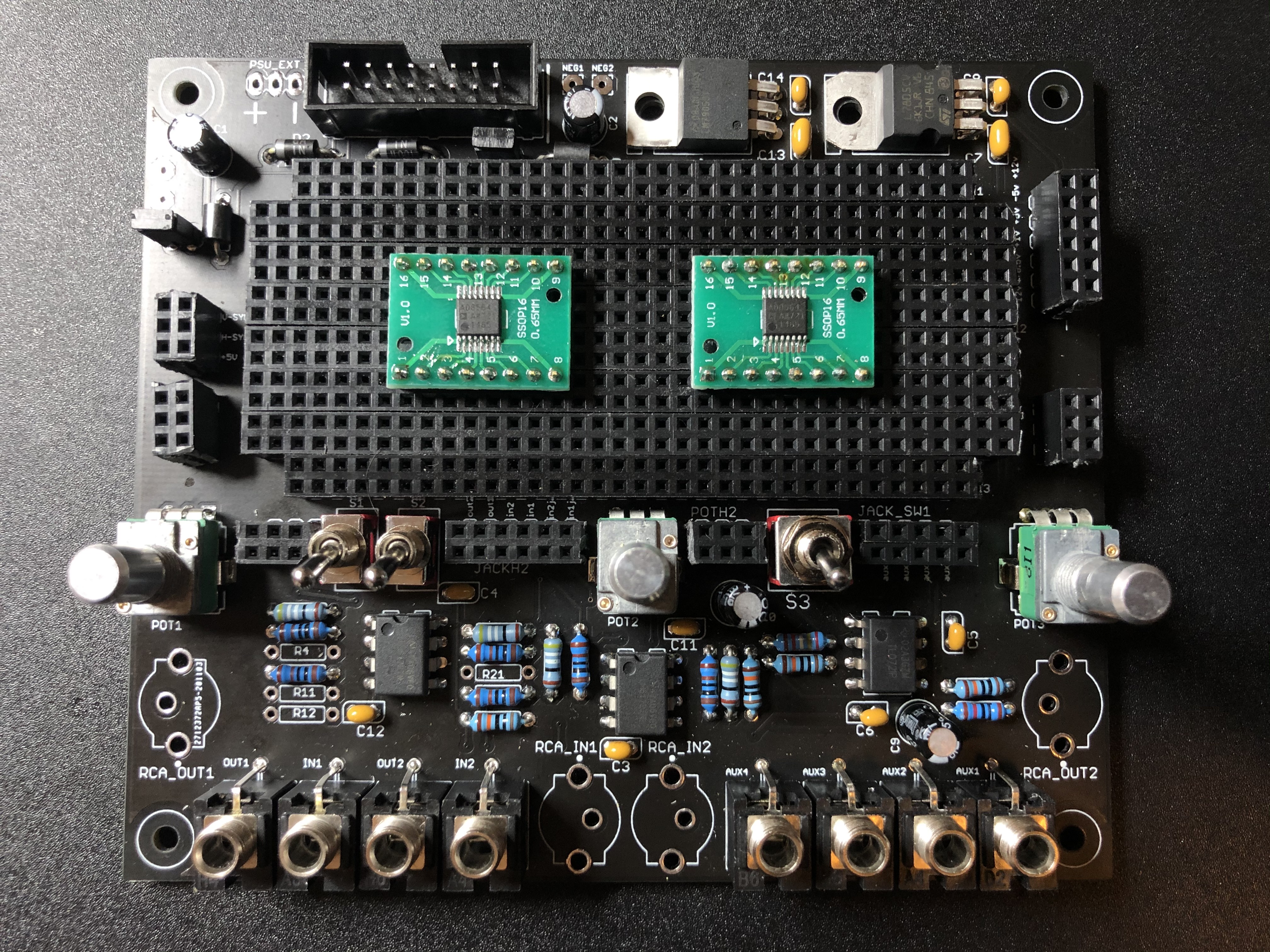
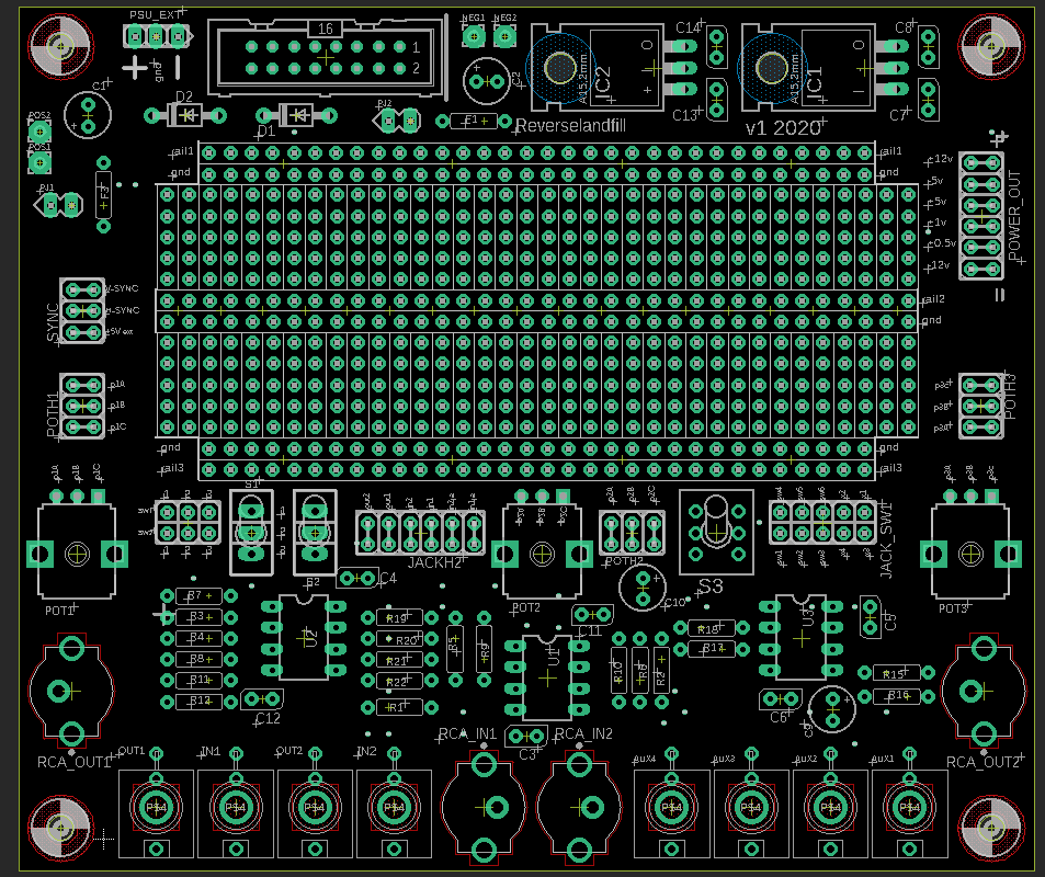
the power out header on the right has these voltages:
-12
+0.5
+1
+5
-5
+12
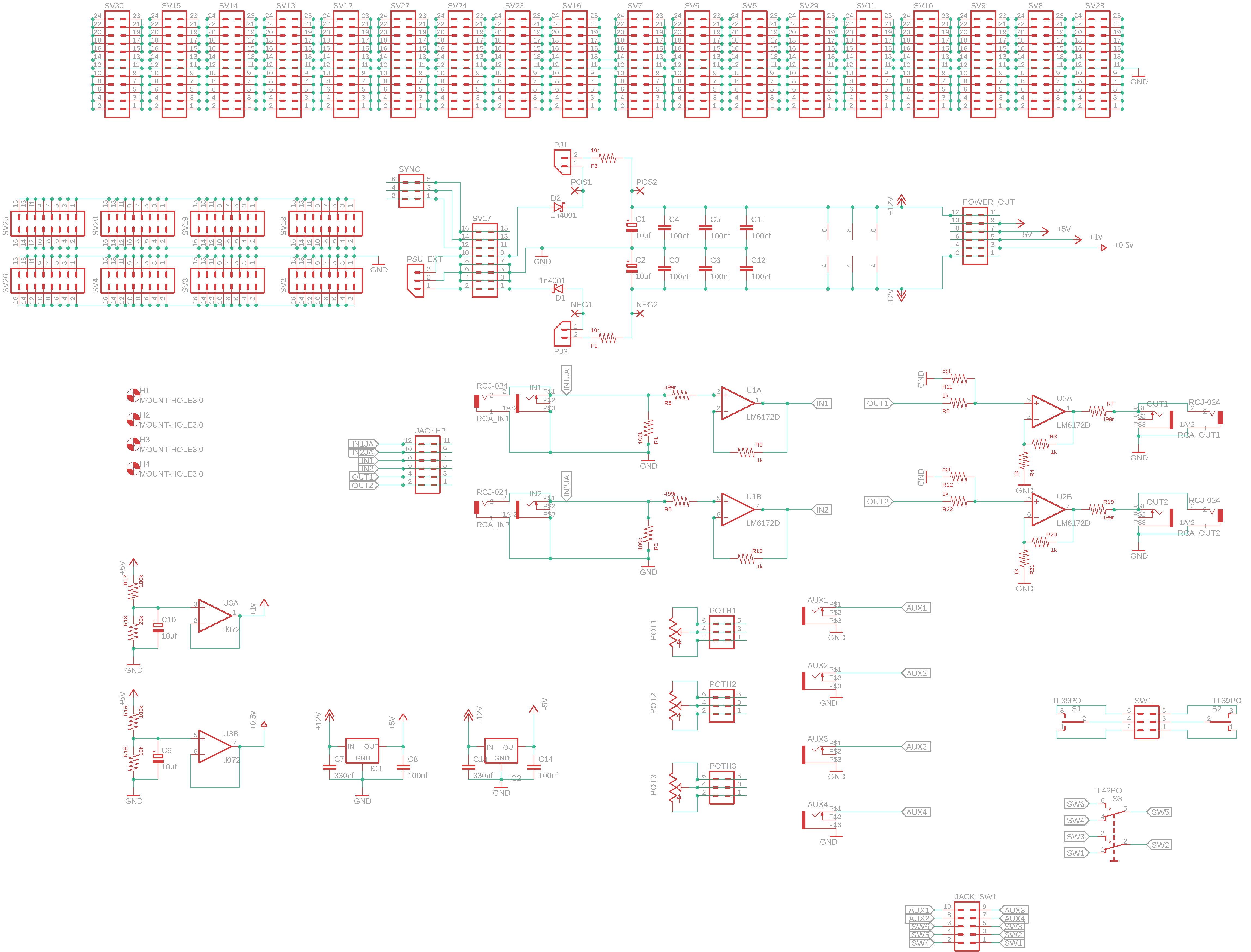
the schematic uses a tl072 for the voltage divider block
I’ll draw in the correct values in the schematic for you, this will clarify it.
I tested all voltage levels, they are correct.
1 Like
version 2 schematic. (high res file)
ps: is there any need for -0.5v or -1v? I did not add this. maybe you can do it yourself with the provided -5v . I haven’t seen it much in the Castle / Cadet schematics.
1 Like
-1V would be good for invert+offset to keep it within 0-1V like in @syntonie’s VU004.
1 Like
My opinion is no - it’s not that commonly used, and when it is needed it’s very easy to derive from +1V.
Having +1V for a basic starting point for other voltages is worthwhile, and +0.5V is the second-most useful because it’s a building-block for logic circuits (like Castles).
That said, given you can just change the resistors to adjust the voltage it might make sense to have one op-amp configured as a positive rail and the other as a negative? Or if you want a deluxe version then make it configurable so each rail can be positive or negative depending on which resistors are populated. I hope that makes sense - if not let me know and I’ll draw up a schematic.
1 Like
please show me. I have made a sim , but I’m unsure if I’m doing it correctly
1 Like
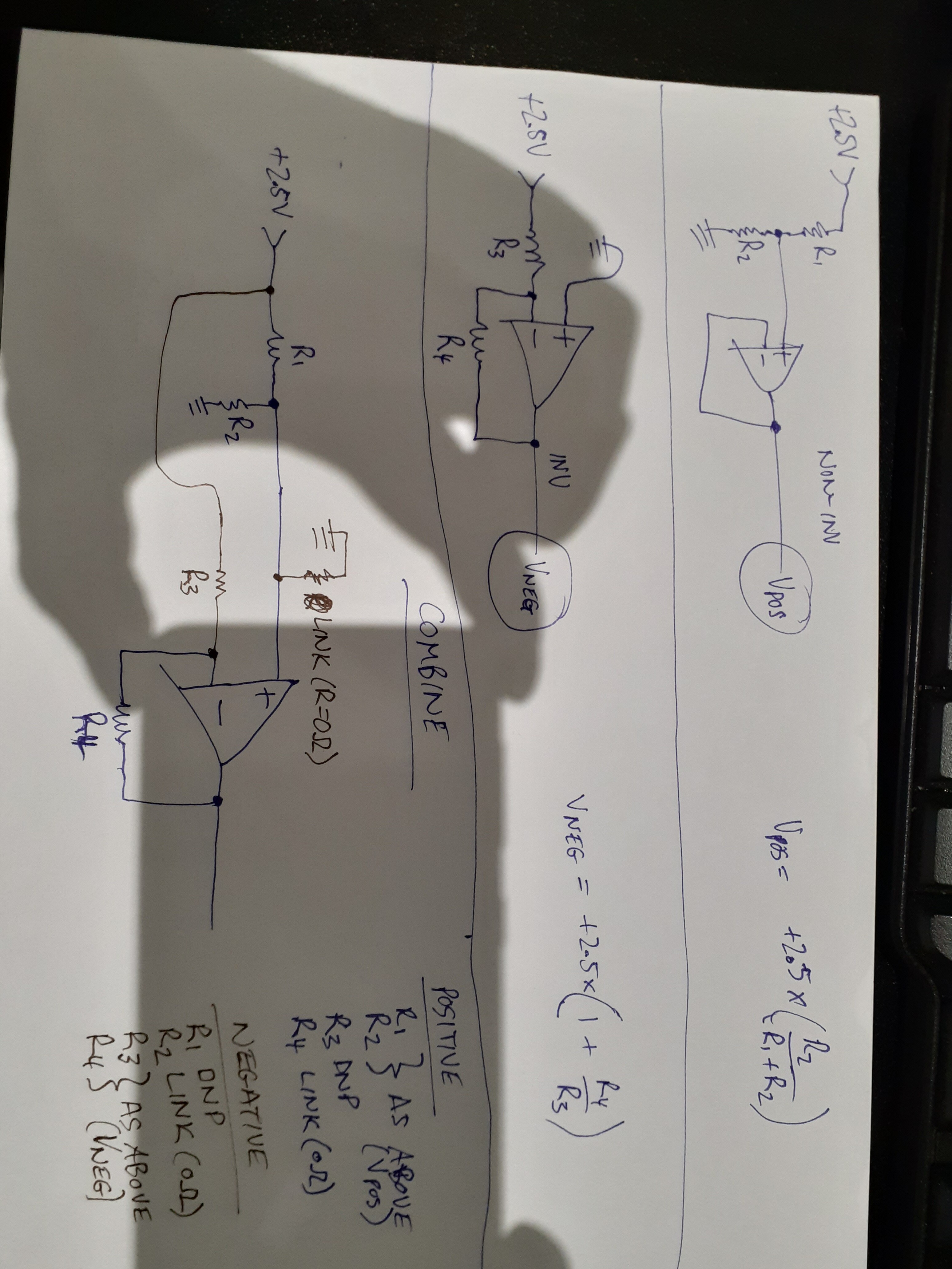
That’s a funny photo, my hand is eating my phone ![]()
Sorry that is laid out for a TL431 generating the +2.5V. But it should work just fine with +5V, just change the formulas.
1 Like
What kind of circuit would require the “combined” arrangement in your diagram @VisibleSignals? I’m a complete electrical noob so I’ve no idea when the inverted & non-inverted would be used either. Just really curious.
The “combined” version offers both configurations on one pcb layout. You will only populate one configuration at once. Choose either “Positive” or “Negative” configuration.
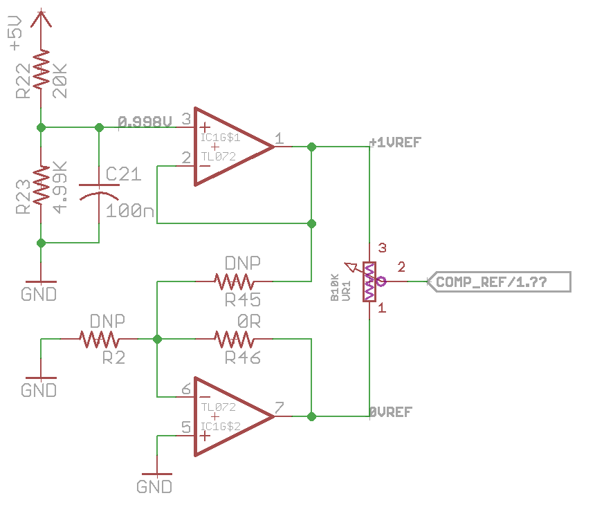
Here is the schematic I have used for the threshold pot on my RGB Selector WIP. For the purposes of the board, I have it set up for the pot to sweep from 0 to +1v, but by swapping some of the resistors, you can make it do anything from ‘-5v to +5v’, ‘-2.5 to +2.5v’ and most anything in between.
2 Likes
Thanks @Fox 
It’s cool to see a real world example.
1 Like
The Vneg formula should have a minus sign sorry. It was very late when I scrawled that down, and of course there is a limitation I should have pointed out: the magnitude of the negative rail cannot be less than the 2.5V (or 5V) reference input, because the inverting op-amp in that circuit cannot have (inverted) gain < 1. If you add another resistor to ground from the IN- on the op-amp it should be possible to get lower voltages but the formula is more complicated so probably just need to fiddle with resistors to work it out.
I highly recommend trying this all out on a breadboard (or a simulator) to learn more about it! These sorts of op-amp building block circuits are important to understand and a first step towards designing your own modules. https://www.electronics-tutorials.ws/opamp/opamp_2.html
1 Like
Cheers Adrian for the correction & especially the tips & link. I’ll definitely try breadboarding it in the coming weeks. Winter, the time for learning & focused attention 
6 Likes
I’ll grab a few of these as well, always love your work! But will batch up a bunch of your stuff for combined postage: just assume a 3-monthly “one of everything” order from me 
2 Likes
ha! the same with your stuff
more economic and ecologically
1 Like
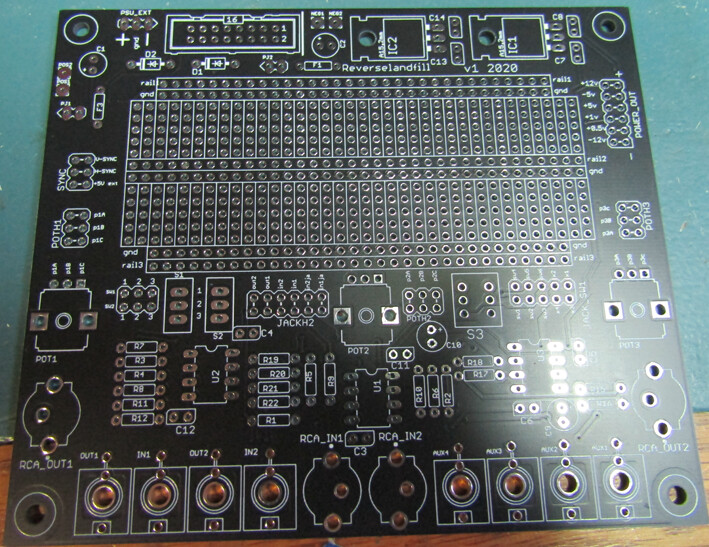
version 2 (although I forgot to update the version number on the pcb..oops)
the solder area markings are printed on both sides of the pcb.
all pads are labeled better now.
5 Likes