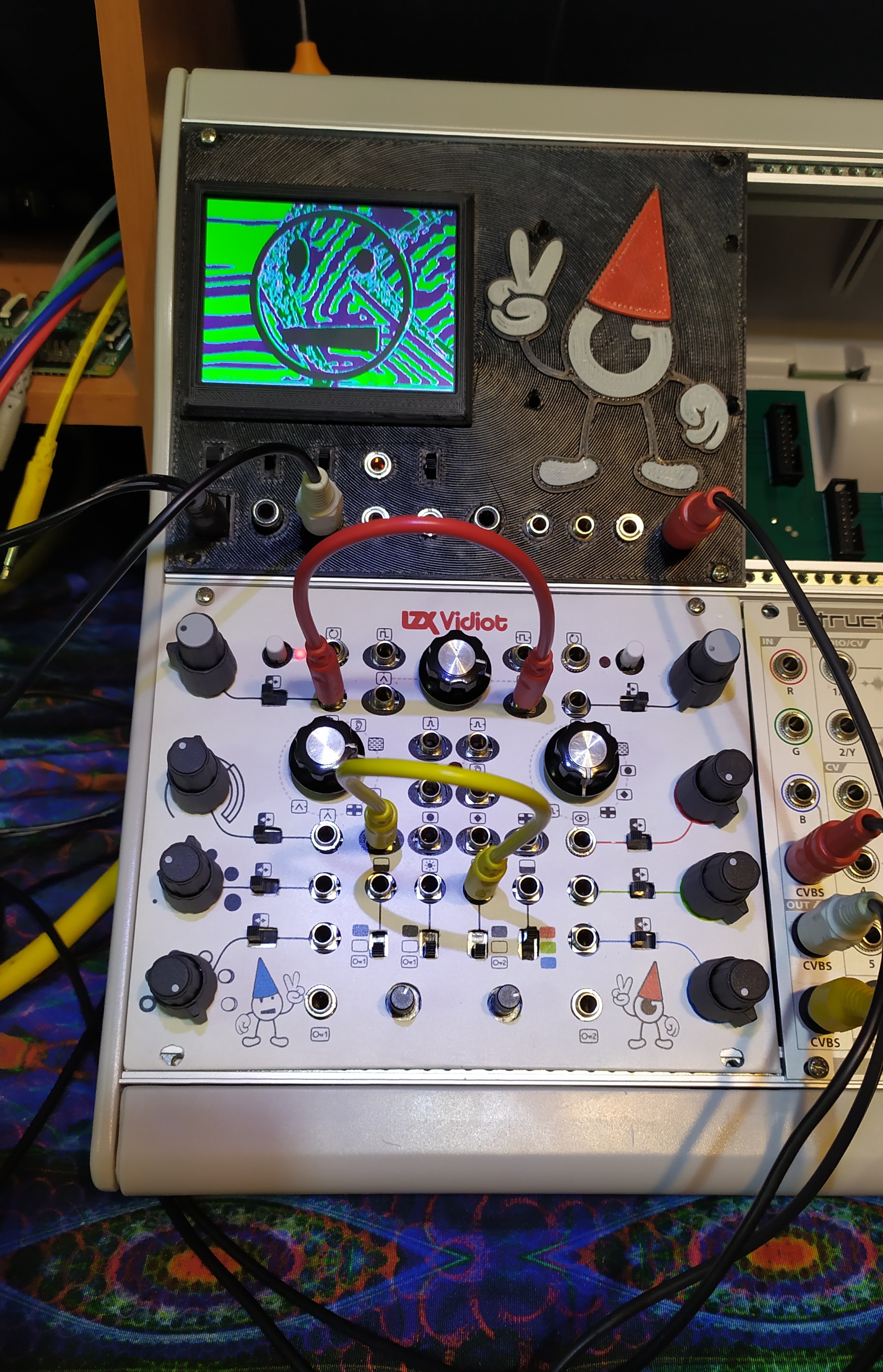
My first attempt at a custom panel. Laser printed glossy paper applied to hand drilled/filed steel plate and sprayed with matte clear coat. I know the bottom edge is F’d. The Vidiot guts barely fit between the rails, and I was not ready. I’ll make a new one where all the screws fit maybe, later… Above is a WIP 3D printed back panel with a 3.5" preview monitor and a nice big eyeball dude with room to mount a rPi underneath for waaavepool n stuff…
19 Likes
That is ingenious, I love that it’s hand drilled and finished - well done!
How messy is it underneath? Show us some pics
2 Likes
This looks amazing!
Have you got a breakout panel for all of the inputs from the rear?
1 Like
@Marizu The black 3D printed thing with a screen above the Vidiot is the back panel.
4 Likes
@Rik_bS No mess just the sexy red vidiot board with stock ribbon cable to back panel. The only “mod” to the Vidiot guts was to solder a small cut off end of an RCA cable to the input loop connection for the screen. Going to add a switch and another connection to the color output since I’m mostly using the RGB outputs to Structure now.
3 Likes
Bravo!  Looks rad. Well done!
2 Likes
The preview monitor is a nice touch. Bravo!
4 Likes
Super job! The monitor is very nice.
1 Like
@j4s0n Nice work! Looks great, and similar to the original! I like the different style knobs on the selectors. So whats the difficulty rating on such a swap, and what can we offer in exchange for a set of these panels? Seems like an excellent solution to modular integration and travel.
@j4s0n - this is a rad finish.
I have been headed down a similar path to eurorack, and havent really decided what im going to do with the remainder of that area…
however - ive hit a snag regarding the rear panel alltogeher
Upon opening the unit, I do not have a ribbon cable, just a very fine pitched ( 1.5mm?) 2x8 right angle pin header and socket. eep.
has anyone else gone this road?
does anyone have any clue what the pitch of this connector might be?
my caliper says 1.5? 1.3? it cannot decide.
is there any reason why i should not just install a ribbon connector into this variation of Vidiot?
thanks!
@dubpixel Mine just has a standard 16 pin eurorack power cable going between the boards. Can you take a picture? Or, maybe ask LZX directly? Contact Us – LZX Industries
@Tremendm_Labs Thank you! Please excuse the delayed response. Those are some old Radioshack knobs I had in the pile here. They’ve been on a few different projects over the years. Not really sure how to rate the difficulty. I’d say it depends on your experience with such things. For me it was not “difficult” at all. Just time consuming but, fun! I hadn’t really considered making any for others but, I will share my CAD if you have access to a 3D printer and feel like DIY. If I would have purchased a Shapeoko instead of Chromagnon and TBC2 pre-order, maybe this would be a different story. Oops! 
i saw this post digging around - betting this is from the earlier design.
Vidiot - Troubleshooting - #10 by creatorlars?
aaaand based around the way things go in parts land i have a feeling its a 1.27mm 2x8 header. (0.050" derp). idk what i was really thinking 1.5 1.3 - lol.
neither is logical because they both convert to something wacky when in inches. because inches is still a thing…
i’m hesitant to bother LZX support (with all the other shit their dealing with atm…) with a ticket regarding essentially me voiding my warranty (albeit in the name of greater good). i will ultimately be prepared for the consequences of what extending the ribbon means - but it may not even come to that.
TBH i think that the angle of the 2x8 header (and the subsequent mating ribbon) makes vertical clearance a no-go. i have not triple checked my math - but will report back when i do.
even if i do not assemble it into ‘rack-mode’, generating the front panel in eagle (with help from fusion) has been fun. the crossover between the two softwares still sucks (understatement) but its been interesting.
nevertheless for my skill set and tools in the shop, this mod, gets a ton easier when i have someone else’s ‘robot’ do the panel drilling (as well as the artwork for that matter) .
you made reference that main-board clearance is dodgy - but im guessing not impossible?
i’m waiting for a knurled nut driver to finish removing mainboard from existing panel. i need to check it against some mockups of the panel i have , and adjust the placement of hole grouping versus the ‘center’ of the mainboard between the rails. this will also help to inform me if i can actually fit my version of the dang thing with the ribbon.
regarding the alleged part(s)
samtec makes a line of 1.27 headers and they are (for a header) very expensive. like 2.50-3.75 each end. the ‘dragon eye’ or some nonsense line ribbon cables for this pitch are just unholy as well. pin to socket 1’ will be like $20 uSD. ffs.
i havent dug around digi or newark, but mouser not cheap!!
normally with this tolerance id just order the part and try it - but its a lot to spend.
Itd be wild if yall were willing to customize other peoples vidiots for this
I’d need your “guardian” to sign a permission slip for that field trip! But, if we could get a precise layout from LZX (or @dubpixel if they work it out), frontpanels.com has no minimum order qty… or I’d be glad to do it if/when I get a CNC machine, for a fair price. Making just my top panel by hand was quite the task, and it is far from perfect. The 3D printed part is fine but, it’s 3D printed plastic… Other option might be to sacrifice the original case, just chop off the top and bottom edges and drill some screw holes, not sure about the back panel though. I wonder if it would fit in a 1U row? My cases don’t have those so…?
Very close.
It mostly comes down to bumping up tolerances on holes and maybe shifting the gap between rows in one location. It’s all parametrically modeled in fusion and left mirrors the right. Currently the spacing on that mirror is maybe a touch off. But also it does fit.
Moving on To the rear panel next.
Plan is to make 3 versions.:
1 is blank in the remainder space
1 is a small preview monitor,
1 will have some space for 1RU tiles (provided my cnc guy surfaces and gets me the parts back I had cut)
Nevertheless you will need some HP! The output board doesn’t fit vertically so you got all that extra room above it to have fun with. I probs won’t spare the space to put it in my main system but it’s been/is a fun project to be working on.
I’ll be putting the final proven designs out
free on the GitHub. They will feature the original LZX art. Lzx has asked (quite logically) I/we not sell units with their art. so y’all can go nuts If you print your own.
To be clear, this is dicey with a rev1 unit. rev2 is way easier.
For the r1 I have yet to get the nerve up to desolder the right angle 0.05 header and reverse its direction and add a ribbon cable (damn pricey one too!) otherwise it’s impossible (or frighteningly tight) to fit between rack rails. I just need a calm day to spend some time at the bench.
13 Likes
Looks Great! Except the pill shapes around the jacks should be filled in for outputs and outlined for inputs.
1 Like
Hey @dubpixel, amazing work here! Did you have a chance to post your design on GitHub? I’m gonna do the same for my Vidiot, installing it closer to the other LZX modules in my synth :))
Thanks!
1 Like