Visual Cortex Output issue

I’m having an issue with the composite and YPrPb outputs from my Visual Cortex (VC). The output image looks as though their is a sync issue, or perhaps a power starve issue.

Here is the signal paths I’m working with:
Roland P-10 -> Ambery SDV1 Composite to YPbPr adapter ->VC YPbPr Inputs
VC RGB outputs -> VC Channel A RGB inputs
VC Composite Output -> Panasonic BT-S901 Production Monitor
VC YPbPr Output -> Sony PVM-8045Q Production Monitor
All knobs and switches on VC set to default

The resulting image looks like this, with the composite image being perfectly still and the component image flickering somewhat:
IMG_20190528_201353

The image on the P-10 internal LCD Display is this:
IMG_20190528_201414

Here’s where it gets weird: If I turn the “Video Output Fade” on the P-10 towards White (brightening the image), the image stabilizes, like this:
IMG_20190528_201427

I’ve also tried output from a Roland V-4, and while it is slightly better, it still shows this sync issue. I’ve also tried output from a small portable recorder (EZCap 271) and that shows the issue as well. When I use just a composite input into the VC and then the Luma output, I get the same issue. The sync light on the VC stays lit green through all of this. Here’s a picture of the configuration:

I was thinking perhaps it was a black level issue but I couldn’t find a guide on adjusting the trim pot. I tried changing it a little anyway and it had no effect. Anybody have any ideas what’s going on?

Some further information: Following the Visual Cortex Basic Patches document, I followed the instructions for “07. Matte Generation”. Starting from all 3 RGB knobs at 12 o’clock, I found that I could only get a green matte by turning its knob to about 5 o’clock. Turning Red to 5 produced an unstable flickering image, while turning Blue to 5 produced nothing. Turning Green to 1 o’clock in conjunction with either of the other knobs did produce the appropriate color matte. Is this the intended behavior? Again, I get the feeling that some kind of calibration is off.

Edit: Additionally, turning the green knob to 5 o’clock and the blue and red knobs to 7 produces a green image, but this behavior doesn’t replicate for the blue and red knobs.

Edit 2:And a bit more info. I ran the composite video waveform from a Kramer test signal generator for horizontal color bars into an Analog Discovery 2 digital oscilloscope and found the following waveform:


Here is that same image as it appears on my Panasonic monitor:

The red lines denote the time of one full field (they are ~16ms apart).

Here’s the same test signal sent through the Ambery converter, into the Visual Cortex, and back out via the composite jacks with everything in its default setting:

And how that signal appears on the monitor (it flickers and changes color sometimes):

Outputting directly from the converter via component to a Sony PVM-8045Q produces color bars without issue.

I’m no expert at understanding video signals, but something seems off, as though everything has been transposed +0.3V and then there is like a 0.7V signal overlaid on top. Anyone else have some deeper insight? This seems pretty far from normal behavior.

1 Like

when you say the sync light is on
which LED are you talking about?
the NTSC and the LOCK LEDS?

what is the switch on your ambery converter set to?
also do you press the button after turning it on?
i got very strange behavior out of mine before I had those two things right

Thank you for the reply. The NTSC and LOCK LEDs on the VC are lit, as in this picture:

The Ambery converter is set to YPbPr and the input select is set to composite (the top button selects between the two, with the LED lighting green meaning composite and flashing red meaning S-Video).

However, even without the Ambery converter involved, the waveform output from the VC seems odd. Here are the settings I have to use to output a Red Matte and a Blue Matte, along with the waveforms for each. If I don’t turn up the Green knob a bit, there is no visible output on the monitor. As the amount of green approaches enough to stabilize the picture, the picture is jittery.

IMG_20190529_143927 Blue%20matte%20waveform

Here’s the green matte waveform, which is produced just be turning the Green knob clockwise:
Green%20matte%20waveform

For comparison here is the waveform of blue screen output from a Roland V-4 (no inputs attached):

Compared to the Roland output, the vertical blanking interval for all the VC generated mattes seems to be in the 0.3 to 0.7V range rather than -0.1 to 0.7V/ Additionally, in the red and blue VC mattes, the field information is at a lower peak voltage range than the blanking interval. The green VC matte field information is higher than the blanking interval, but not as high as the V-4 blue waveform.

So it seems to me that even without any external input, the VC is producing malformed video waveforms. If nothing else, I’d expect that the vertical blanking interval should dip down closer to 0V, as with the output from the Roland. Who out there has a VC and a scope and can see if their VC output is the same? Or is otherwise an expert in video waveforms and can immediately see what my problem is?

1 Like

This seems really weird. A power issue seems possible, is the Cortex the only thing in the rack receiving power? Are you able to get expected outputs from patching the Cortex ramp generator, or other synthesized shapes to the Cortex encoder?

As far as waveforms, I think it may be hard to get good measurements of voltage levels and such at this time scale. I received my Visual Cortex yesterday and hooked it up to my Tektronix VM700A video measurement set, an awesome machine I should probably write up a separate post about. Mattes from the Cortex look very stable for me and the knobs give quite a wide range of chroma output when looking at the vectorscope display, it compares quite favorably to mattes from my Panasonic MX50. Hopefully there’s nothing wrong with the outputs on your VC and we can sort out what the issue is.

Thank you so much for the response! My basement flooded after the big storms here Wednesday and it took me a few days to get back to troubleshooting this issue.

I disconnected everything from my power supply except the Visual Cortex. I monitored the 12V -12V and 5V rails from the power supply while playing with knobs on the VC, and the rails were all correct and steady. I also checked all the grounds and they too were all at 0V. Has anyone else encountered difficulty with Synthrotek power supplies and LZX gear? I don’t have an alternative power supply to check the VC with but I might be able to do so later this week.

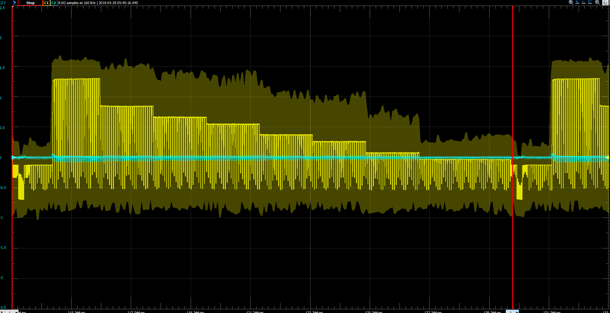
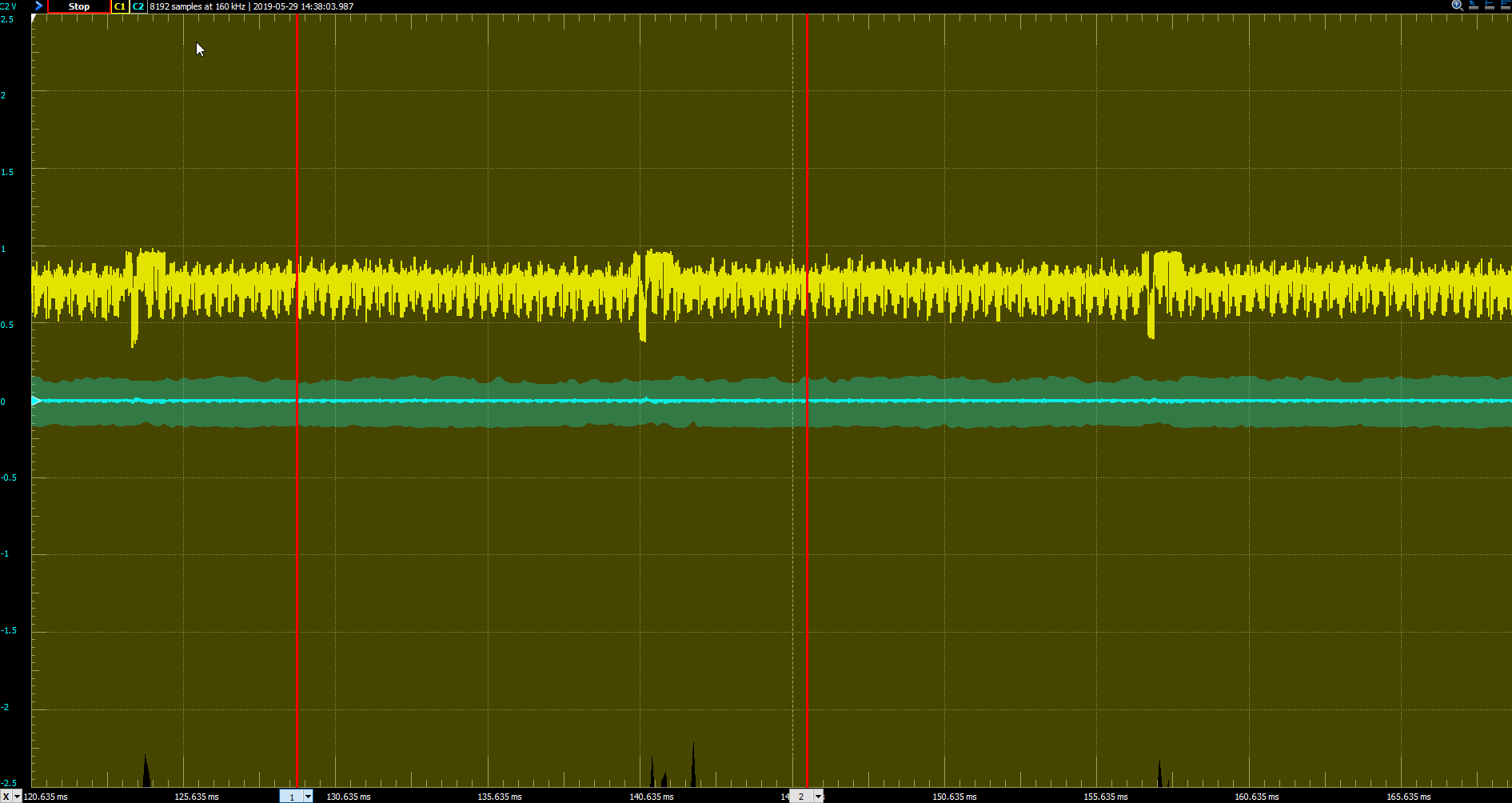
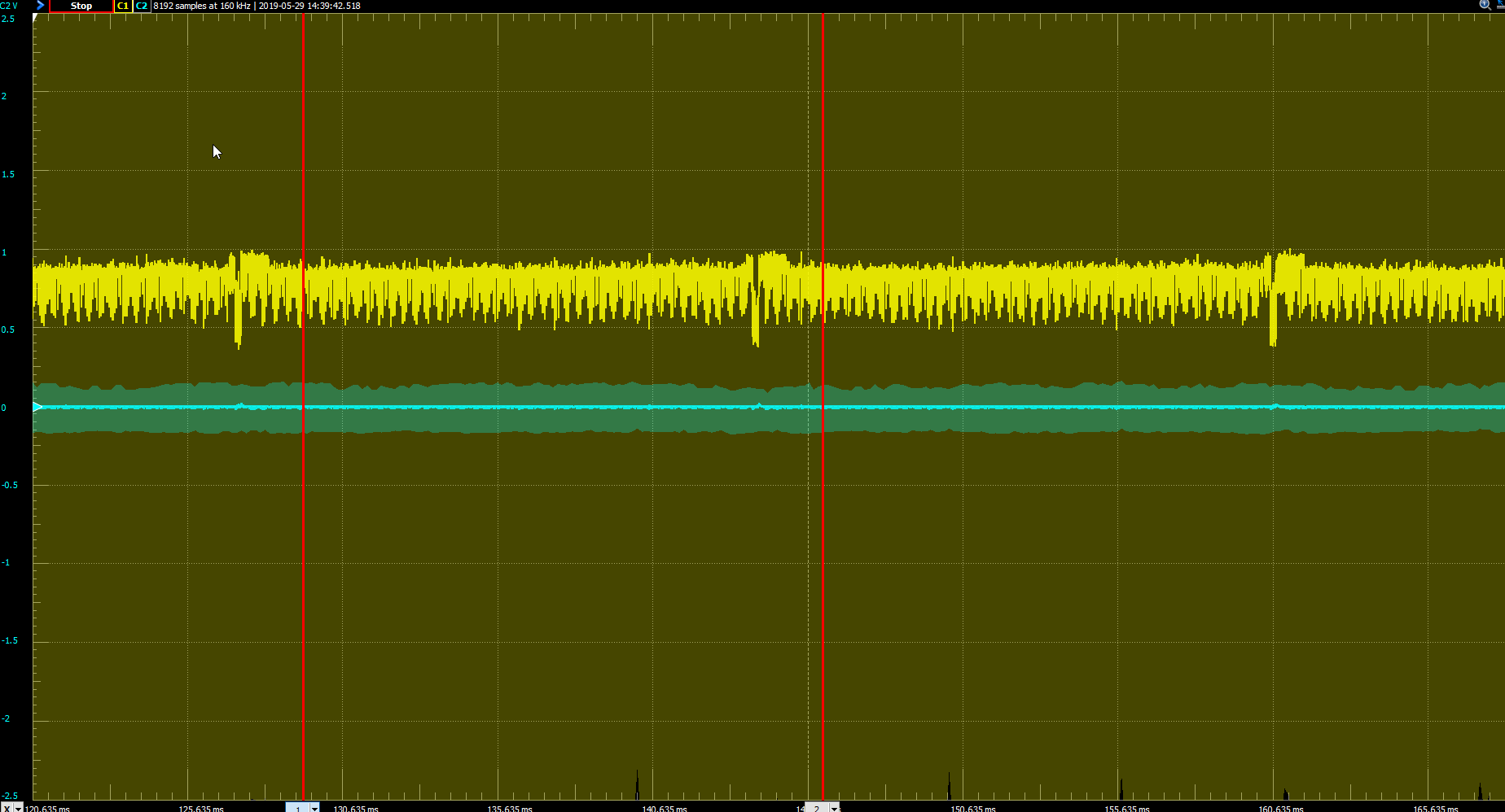
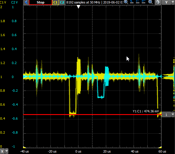
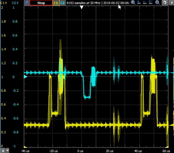
That said, I think I may have identified the issue. I set the scale of the scope to look at individual lines and then offset the inputs from the VC and my Kramer Test Signal Generator set to black burst so that the 0 IRE positions were about even. I then used the VC knobs to try to replicate the way the signal looked from the signal generator. The expected behavior, I believe, is that with the knobs at 12 o’clock, I should get a signal that looks like the one from the test generator. Instead, it looked like this:
VC in Yellow, Black Burst from Signal Generator in Blue, scales identical, y-axis offset so 0 IRE levels match:

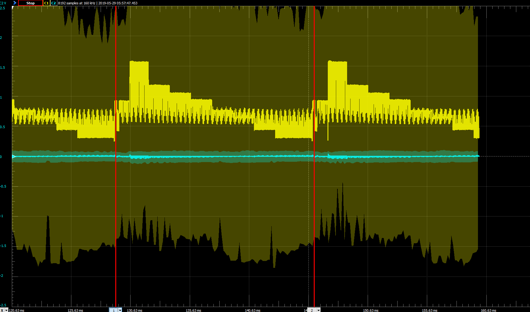
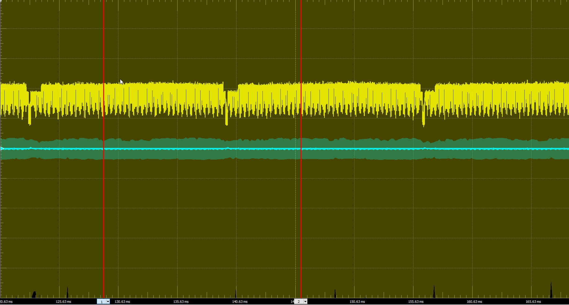
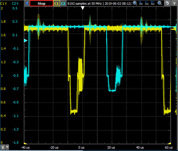
I noticed that the sync level from the VC as well as the color burst seemed to be at about double the amplitude of that from the signal generator. I then tried comparing a white fade from my Roland P-10 to the VC with the knobs turned all the way to the maximum, which produced the following:
VC in Yellow, White Fade from P-10 in Blue, scales identical, y-axis offset so 0 IRE levels match:

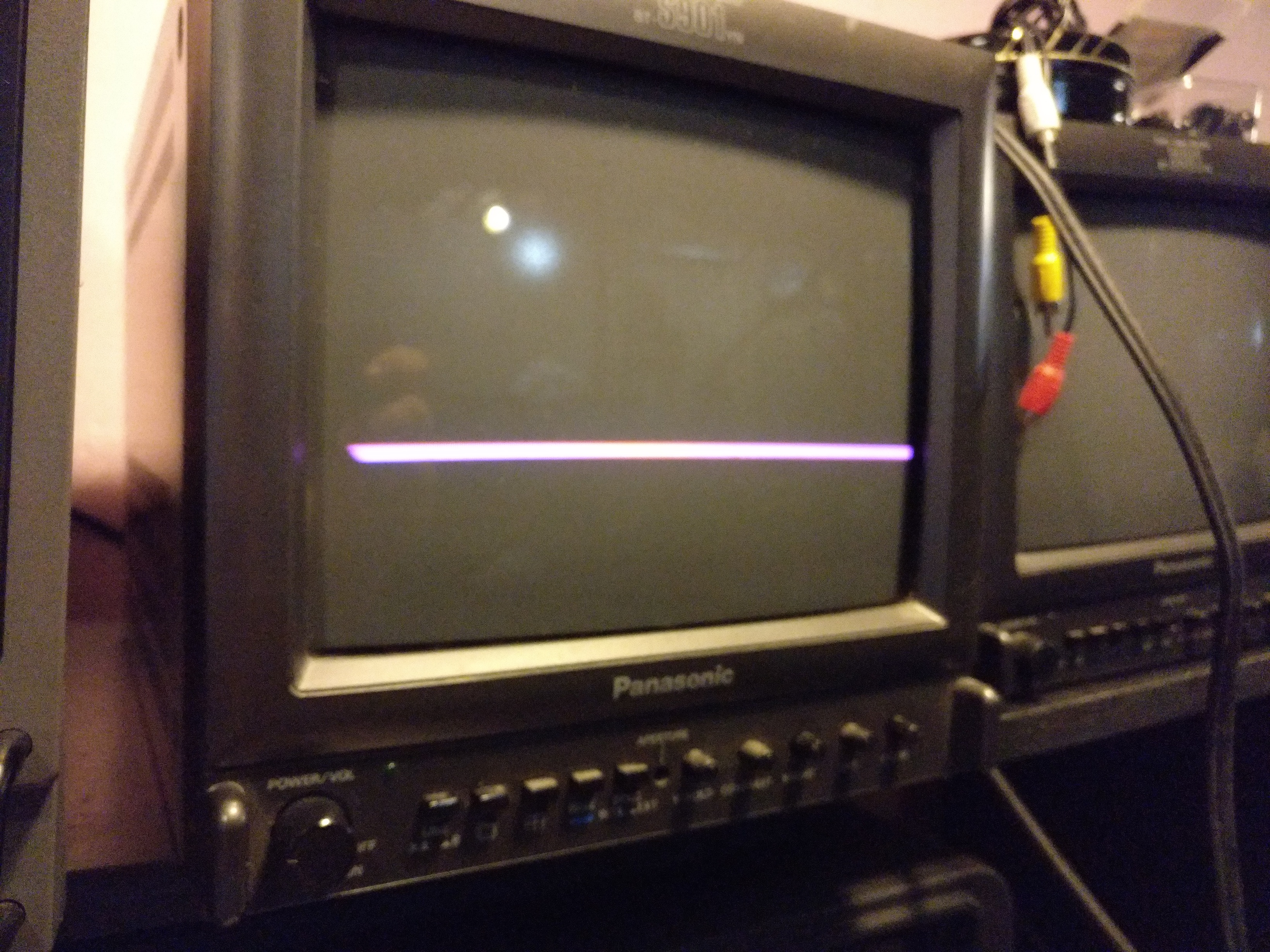
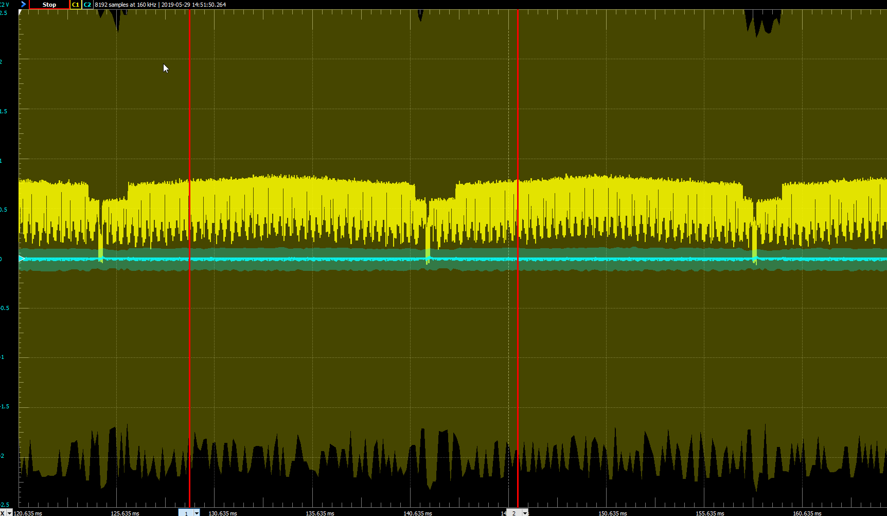
Again, the levels match but the sync and colorburst seem to have double the amplitude. I then tried again with the VC knobs turned to their minimum, which produces no visible video signal:

That seems to be about -0.714 V below 0 IRE, that is -100 IRE, which makes sense if the purpose of turning the knobs in that direction is to remove color from a video signal that is being mixed. From this I can conclude that the range the knobs is covering seems correct, but the “center point” seems off.

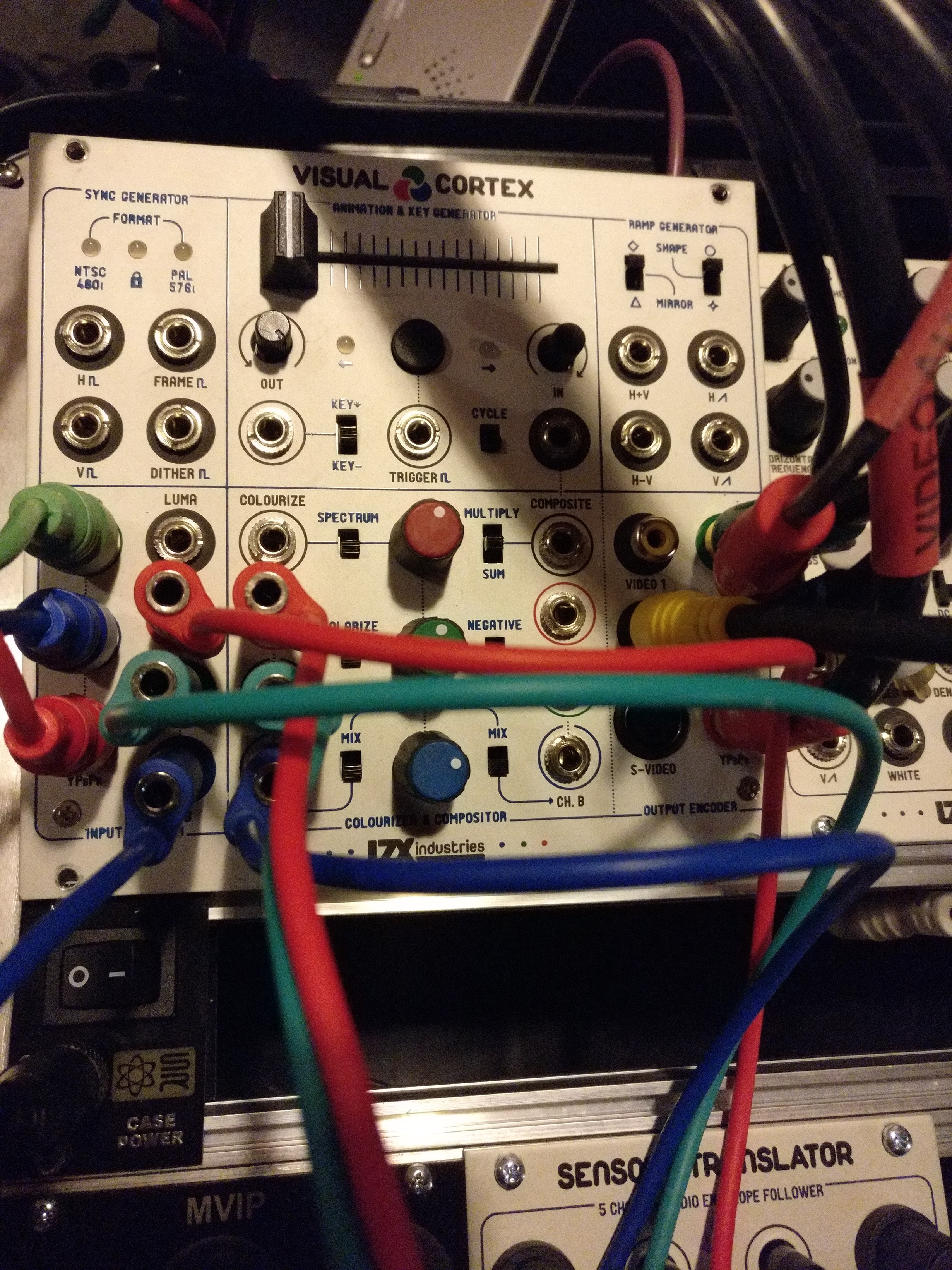
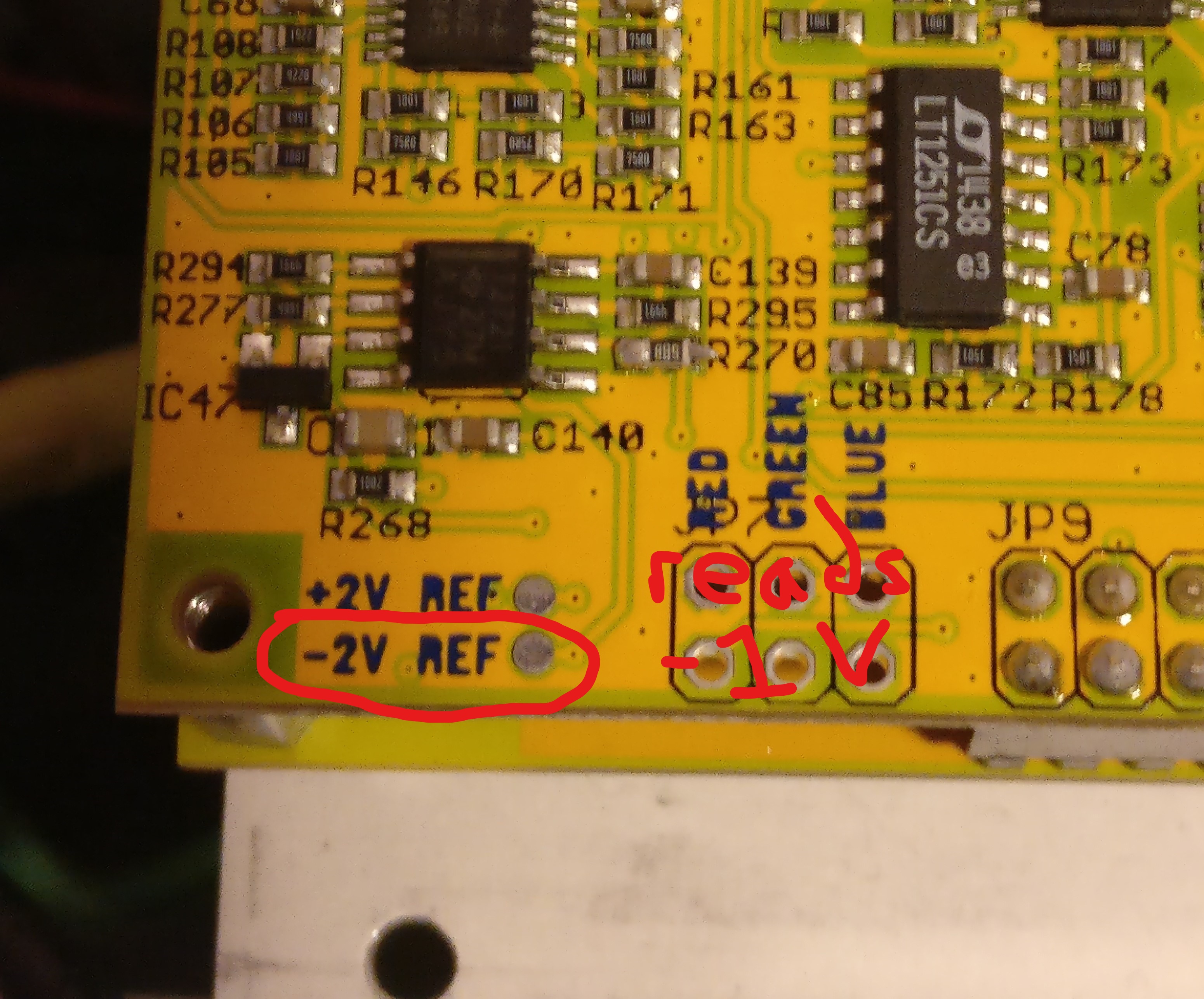
Based on this, I tried adjusting the black level using the trim pot on the back of the VC. This had no effect on the 0 IRE level or the amplitudes of anything. While looking at the back of the VC I noticed a number of what I presume are test points for checking voltages. I decided I might as well check those out, so with the VC secured and powered, I checked each test point using a multimeter. They all matched the voltage silk screened on the PCB until I checked the -2 V spot pictured below. That location read as -1 V compared against multiple ground points. Could this voltage being off induce the output errors / odd waveform behavior I’m seeing? Is there any way this could be a DIY fix or do I have to send my VC in for repair?

please contact support@lzxindustries.net so we can issue an RMA and clear this issue up for you