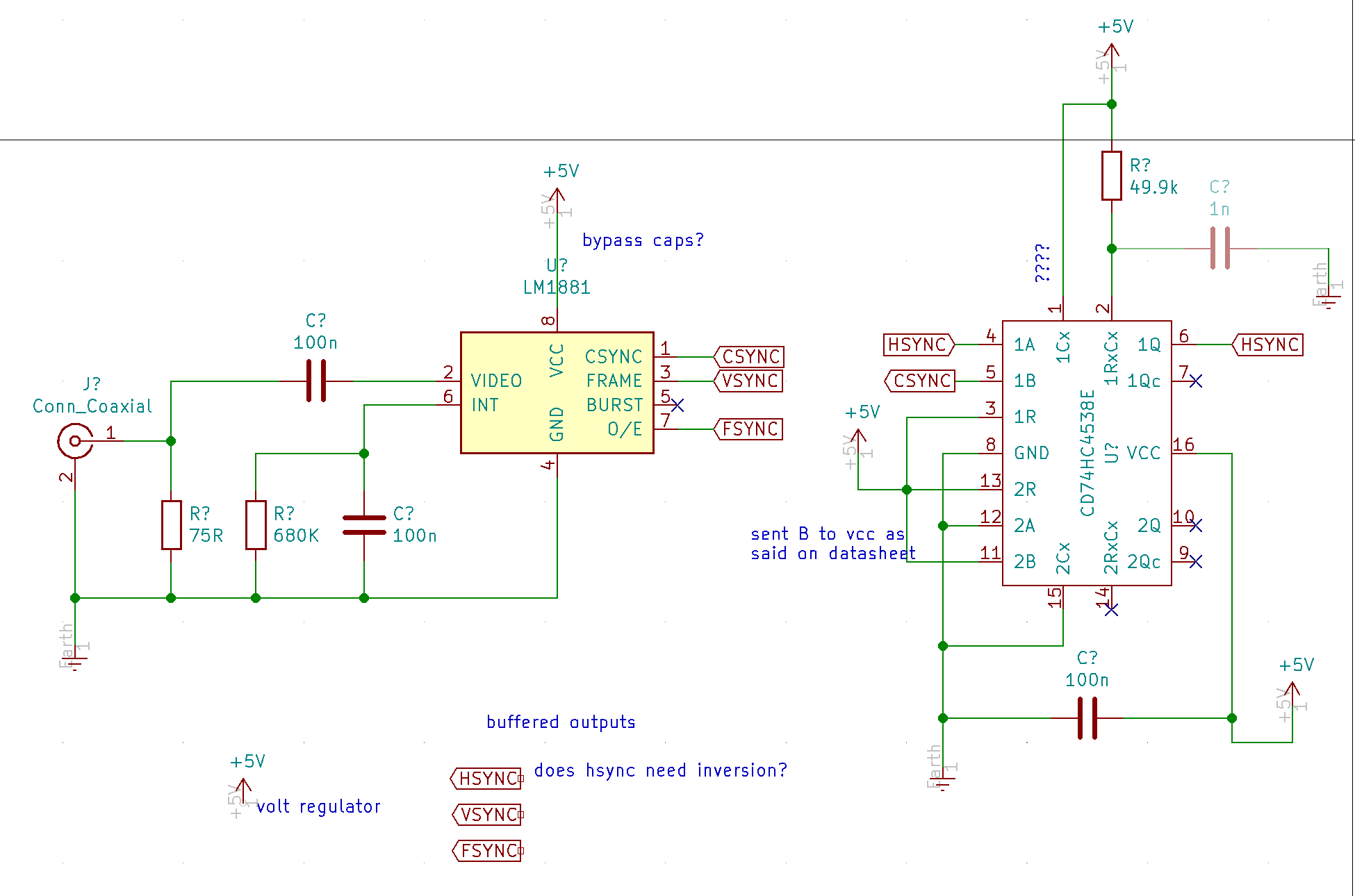
100n bypass cap for LM1881 and in general any V+ or V- pin on every IC. Place it adjacent to the power pin.
If the goal is to reset VCO, S&H, etc. then you do not really need the monostable part (74HC4538.) Just use the CSYNC output as HSYNC. The periods during which CSYNC looks different from HSYNC are during scanlines in the vertical blanking interval (meaning we never see them, any signal in those periods is removed at the output encoder.)
So in your cases listed (resetting a VCO), you can remove the 74HC4538 and just use CSYNC as HSYNC.
Cases in which you’d need the monostable include a genlock clock PLL circuit (like Cadet I).
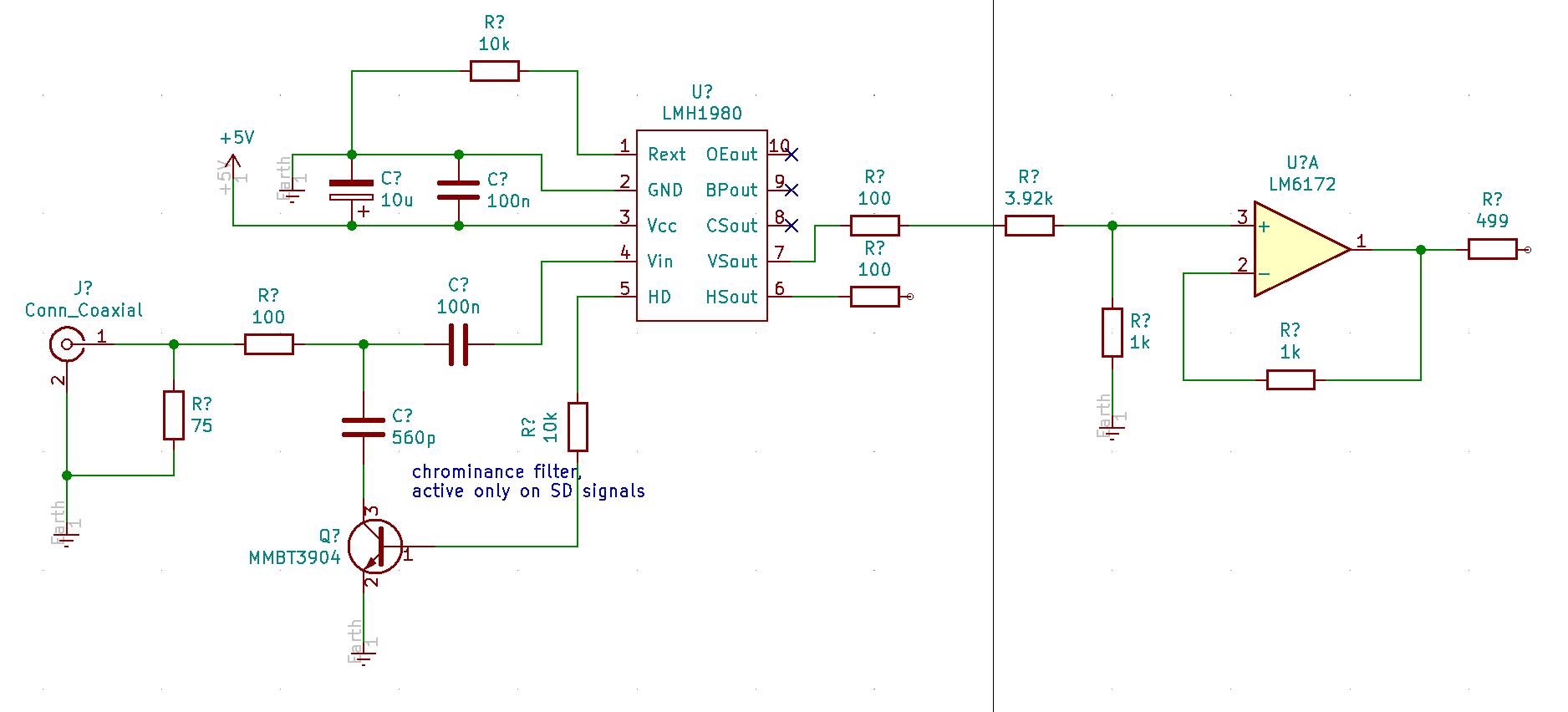
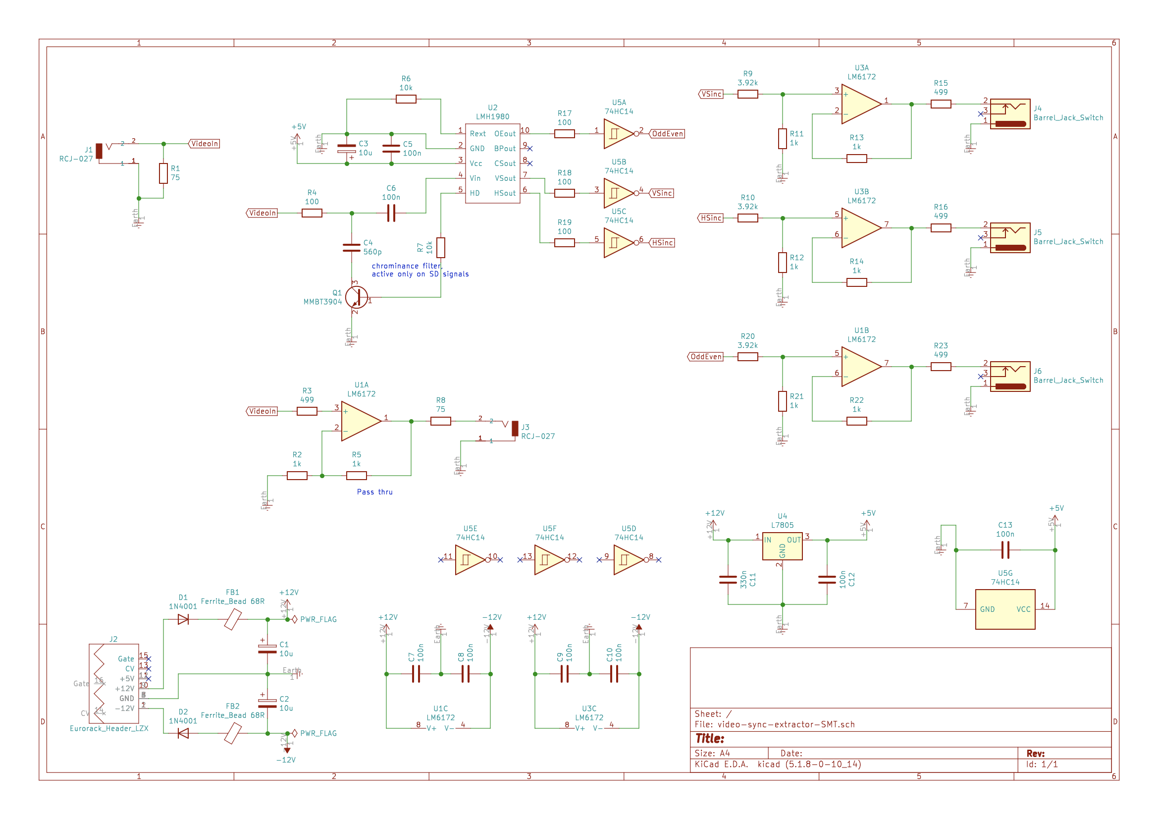
LMH1980 is the preferred sync separator part for Gen3 stuff, if you care about HD syncs! It also has separate HSYNC output, which is handy. Just follow the circuit in the datasheet. It only comes in an SMT package size though.
re: Buffered outputs… these days we strongly recommend you include rear video sync input/buffered pass thru like this on each module that needs it, and just include HSYNC/VSYNC/OFF switch on the frontpanel (rather than patching HSYNC and VSYNC around). That would then select from the LM1881 TTL outputs to control whatever switch is in your VCO circuit directly. This is how the new LZX oscillator works for example – there is a frontpanel sync input, but it is OR’ed with the HSYNC/VSYNC being generated by the sync extraction circuit internally. I should post some application examples.
Thanks Lars, this is a very useful information! My goal is to have patchable sync sources in my system, I don’t have any source of sync except a Vidiot and I can’t build, for example, a Castle VCO because I don’t have compatible sync sources.
One day I’ll probably try to build my VCOs or ramps but not before try to build one of those available out there.
Oh yeah, I read that you said something about this change, sincerely I’m a bit scared of SMTs (I’ve got an art degree nothing techie) on the other hand the circuit for LMH1980 looks easy to setup.
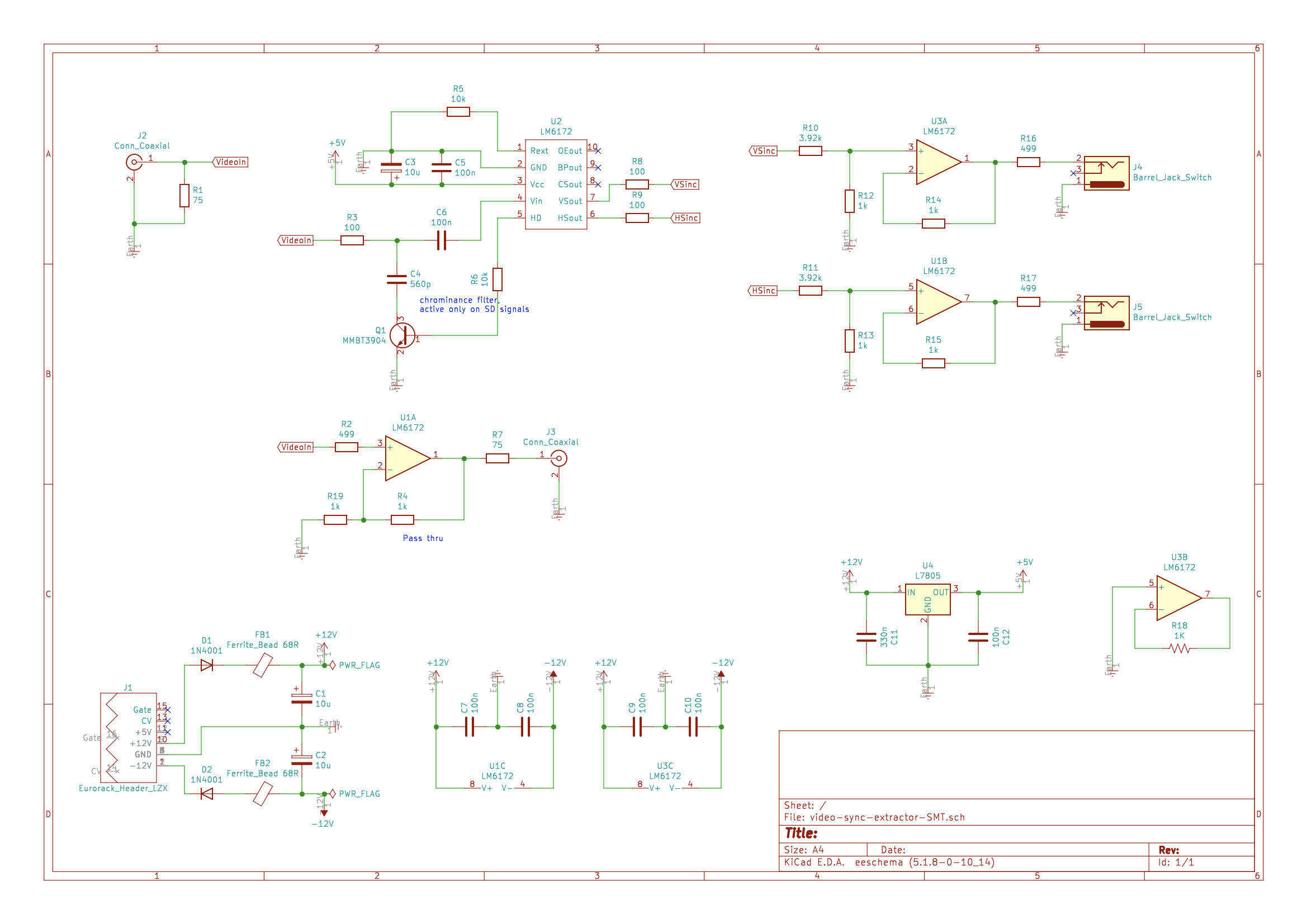
I guess is also possible to leave the HD detect flag disconnected without any issue; then remove C2, Q1, R3, and R10 from the equation.
Cool!! It sounds like a simple LM1881 circuit is exactly what you need then.
If you use the LMH1980 I would keep the HD/SD filter as in the application circuit – it applies some filtering in SD modes to prevent glitches. But if all you need is SD syncs for DIY project, LM1881 is perfect.
Even if I’m not planning to have HD units soon, I want to go through the HD route, I’ll use PCB manufacturer SMT placing service, I guess.
I’m keeping the HD/SD automatic filter, seems smart.
What I can’t understand is what voltage LMH1980 outputs, from the datasheet looks like it’s Vcc dependent, I can’t understand if using 5Vcc it outputs 5V as sync signal… should I keep the Cadet’s voltage divider on the output?
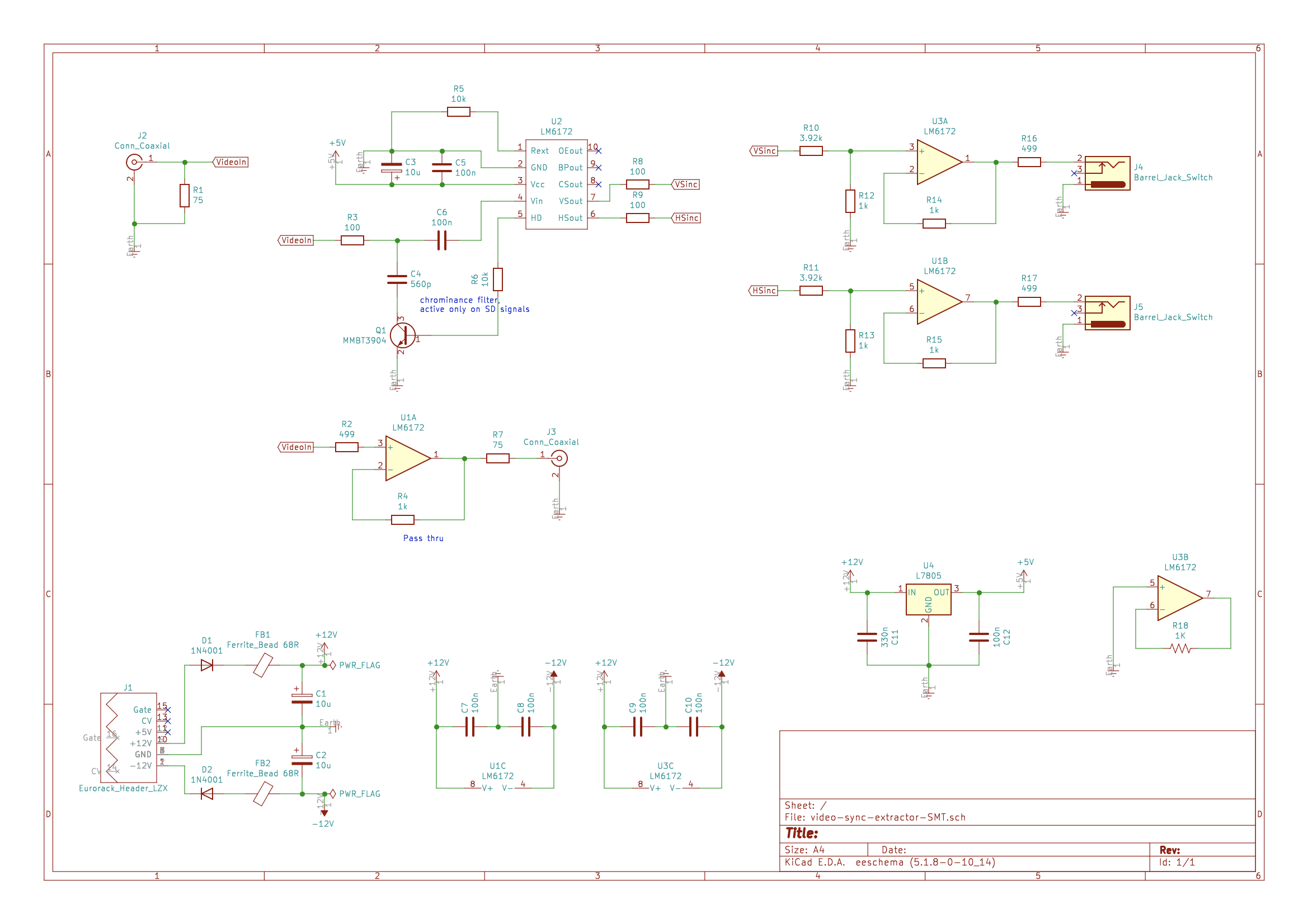
Good work. You can omit R8 and R9 – those are in series with R10 and R11, and aren’t really doing anything in this instance (just have R10 and R11 adjacent to those pins instead.)
In Cadet Sync Gen, Visual Cortex, and Video Sync Generator, the frontpanel sync outputs are inverted, so that they appear as a positive pulse to VCOs. I would use 74HC14 inverters to invert between the LMH1980 and the output buffers if you want to do it that way. A population option is at least a good idea for the PCB design, if you’re not sure.
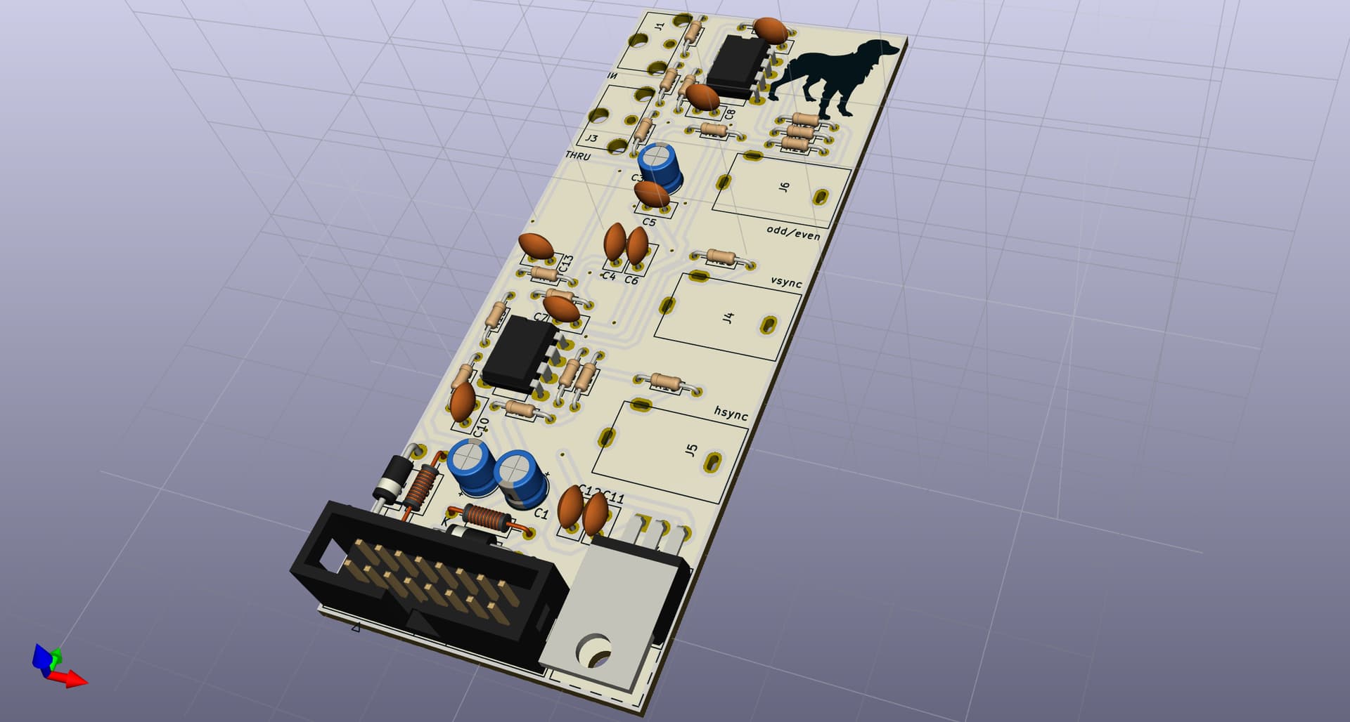
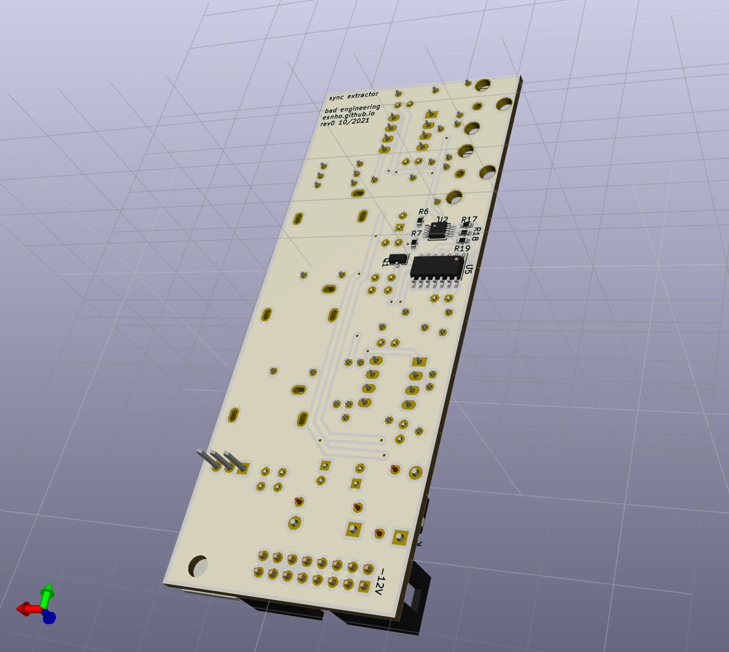
The layout is in vertical style, the PCB is 40mm depth, the RCAs female jacks points downwards, this means that the used RCA cable changes the module depth.
I had to draw RCAs footprints, I want to double check them before send the project out to print.
I never finished a similar design I had been working on. I got busy with work & still need to solve a similar issue in part of my rig.
Lmk if you are gonna sell PCBs, I’ll pick one up for sure.
Also always a reminder I should stop using Eagle and learn kicad- your 3D looks great.
For the Odd/Even out, let’s talk about the inversion –
The output from the LMH1980 will be high when you are in the first field or you have a progressive video format.
Odd/Even inverted (what you have now)
This is an interesting case because the output state only goes high if there’s an even field present. That means it is also a “interlaced/progressive detect.”
Odd/Even non-inverted (what you probably want)
If you don’t invert that output, the output now transitions from low to high at the start of a new frame. This is what is meant by “FSYNC” on Visual Cortex for example. This start of frame event is really important if you want to send a sequencer a “frame clock” that only transitions at the start of an interlaced frame. If you sync a sequencer with what you have now, it would be half a frame off.
In both cases this output is useless in progressive video formats – you’d want to use VSYNC instead. So a mux (ODD/EVEN OUT = VSYNC in redundant states) would be a good idea if this were intended as a product design where you were trying to eliminate null output states. But not necessary.
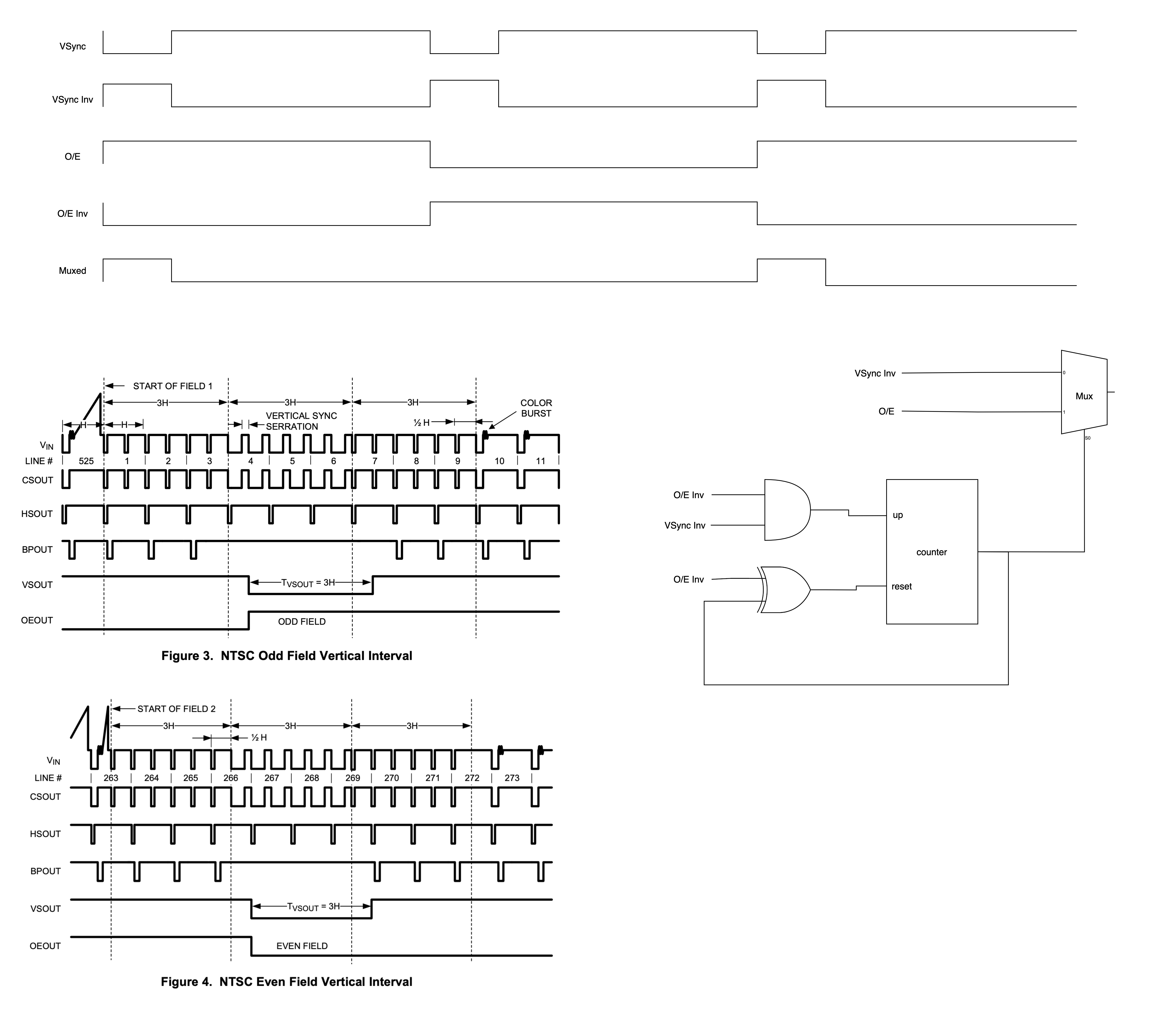
I was looking at the timing diagrams trying to imagine the mux logic.
A = Odd/Even | Vsync
B = Vsync
I’d start sending Vsync to both A and B, if the circuit detects an interlaced frame, the muxer start sending Odd/Even to A and Vsync keeps going to B.
For sure this little logic doesn’t support hot sync source swap (from i format to p) and requires a manual reset (on/off), and starts to add complexity to what I thought be an easy circuit
Probably here I need:
a muxer, preferably with only two inputs
a counter, with less pins as possible
I think that is possible to use booleans to switch back from “interlaced state” to “progressive state”, but probably I need to fully understand the use cases of the syncs and odd/even, below a logic that could work keeping the “state” dynamic, but I’m not sure.
It uses an AND and XOR gates to flip a counter that controls the muxer, maybe is totally wrong, is the first time I try to design such logic.