update.
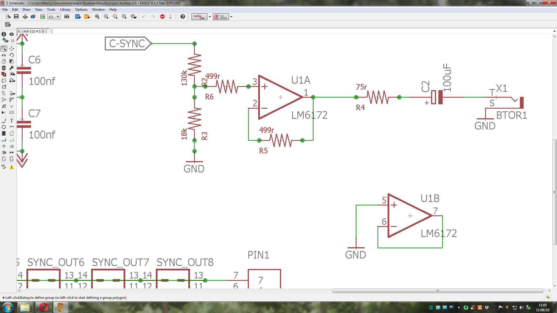
I changed the resistor values to get 0.608V. but with the 499r between I’m unsure what voltage I will get there. I’m not really a math wiz. I guess I can breadboard it.
Do I need to add 1n4001 diodes & ferrite beads at the power connector?
As for the connecting cable:
You mean that one could install a 2nd C1 in the other case and use the sync thru/output from C1 in case 1 to drive the sync input on the 2nd C1? (using a RCA / BNC cable)
That sounds solid.
note: I am deciding between right angled RCA or vertical. I have a lumberg vertical RCA footprint in Eagle. The Mouser part 490-RCJ-044 would also be good. But I don’t have the part in Eagle. Does anyone have this?
I can make it myself, but that will take way more time.
1 Like
another thing:
I am thinking about ditching the 7pin screw terminal blocks and instead adding 3 jack sockets, so that you can connect busboards together using 3 jack cables.
So the 6 sync signals are packed into the tip and gnd connections of the jack socket.
IDK if this is good practice. but having 7 single wires (per busboard connection) might not be practicable either.
The GND connection is then provided by the power connection.
1 Like
I recently bought a 8 pin M12 cable for interconnecting my two cases containing cadet+castle (soon also the sandins) modules.
For now i use an XLR cable cut in half for power, but wanted to get a cable that is not mixed up with other signal types (to avoid accidentally inputing +/-12 volts to some delicate equipment by mistake), and wanted to include the bus sync signals for my other case.
Initially i thought about hacking it in a much simpler way than what i can read in this thread.
I wanted to interconnect the bus sync by just plugging a 16 pin cable into one of the sockets in the busboard, and then use only the sync signals leads from the ribbon cable to feed the sync signals through the M12 interconnect cable (together with power: ground, syncs, and +12V, -12V), throught the interconnect cable, and then on to the next busboard by plugging the sync signals directly to the busboard through one of the 16 pin sockets,(again via a ribbon cable, but only using the sync pins) power goes through screwterminals on both busboards.
I dont se if this should not work, but havent tested it yet..
Will have to read through this thread a few times before i venture into cutting the cable in half and attaches it between my cases.
@creatorlars Would this (going directly between the sync pins on different busboards) be a viable way to get bus sync between cases?
The cable i bought might be of interest to you also. the connector type comes with all different pin numbers, i went for 8 pins.
https://www.tme.eu/en/details/21348485882015/connectors-with-cable/harting/
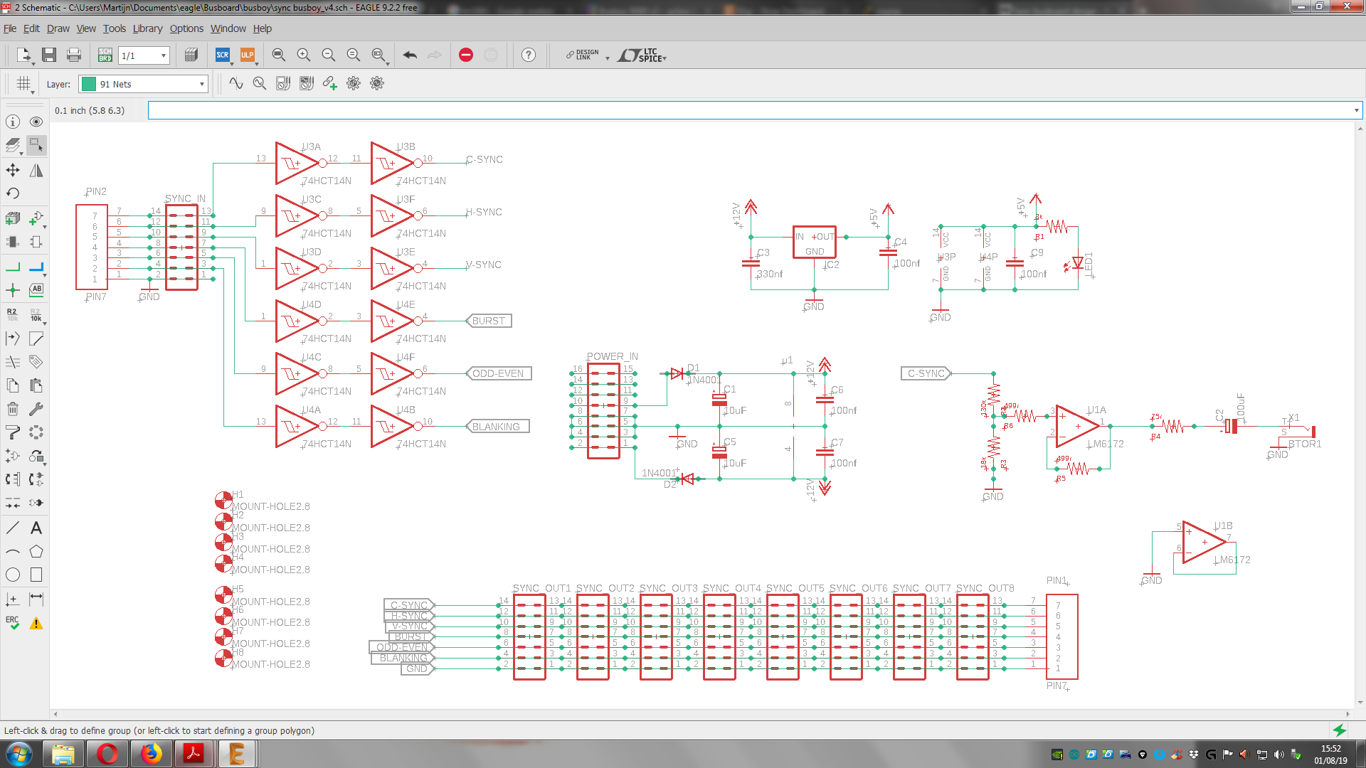
update:
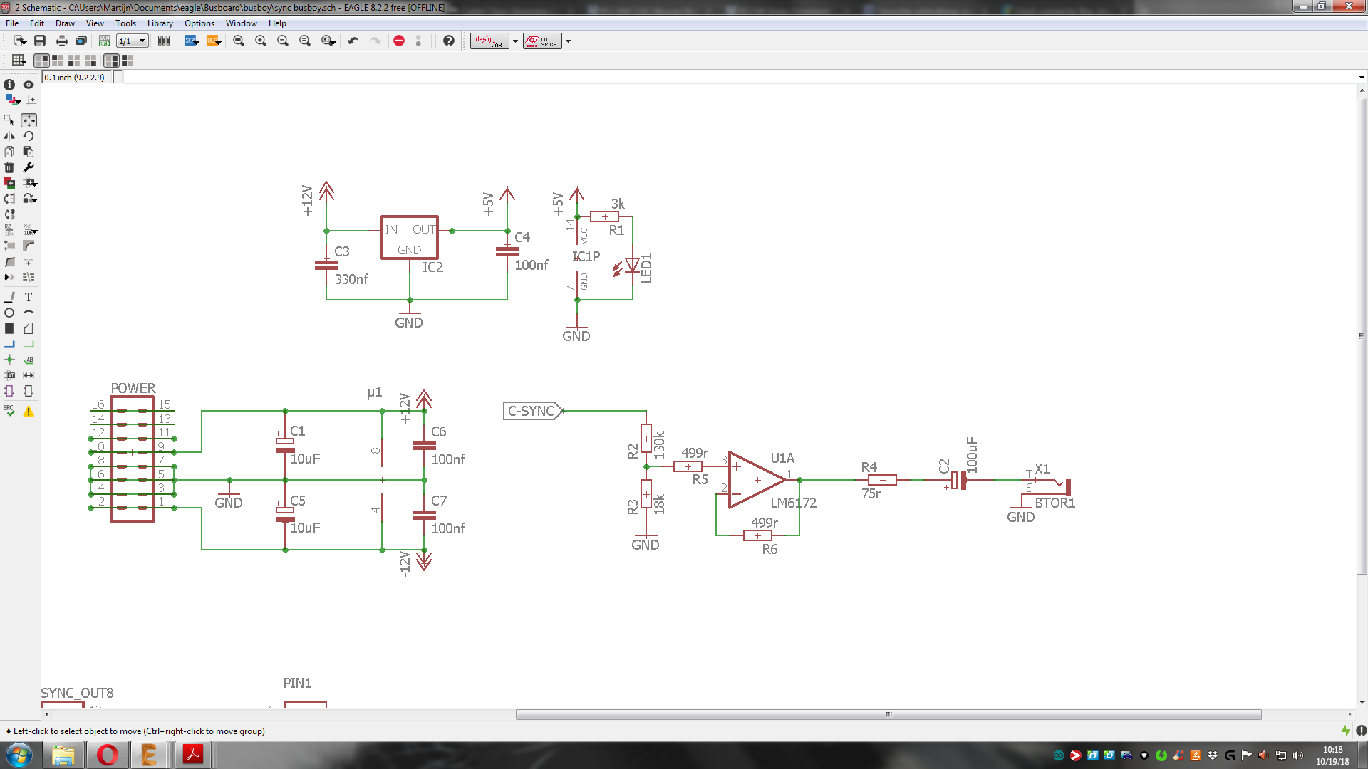
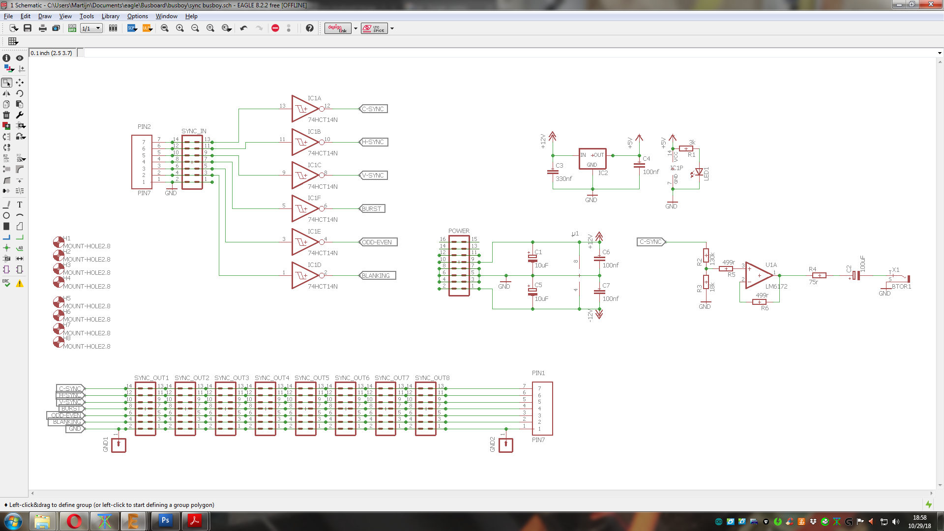
the layout is done. I hope to get some comments on the schematics. is this correct?
if so.. time to send it to China!
2 Likes
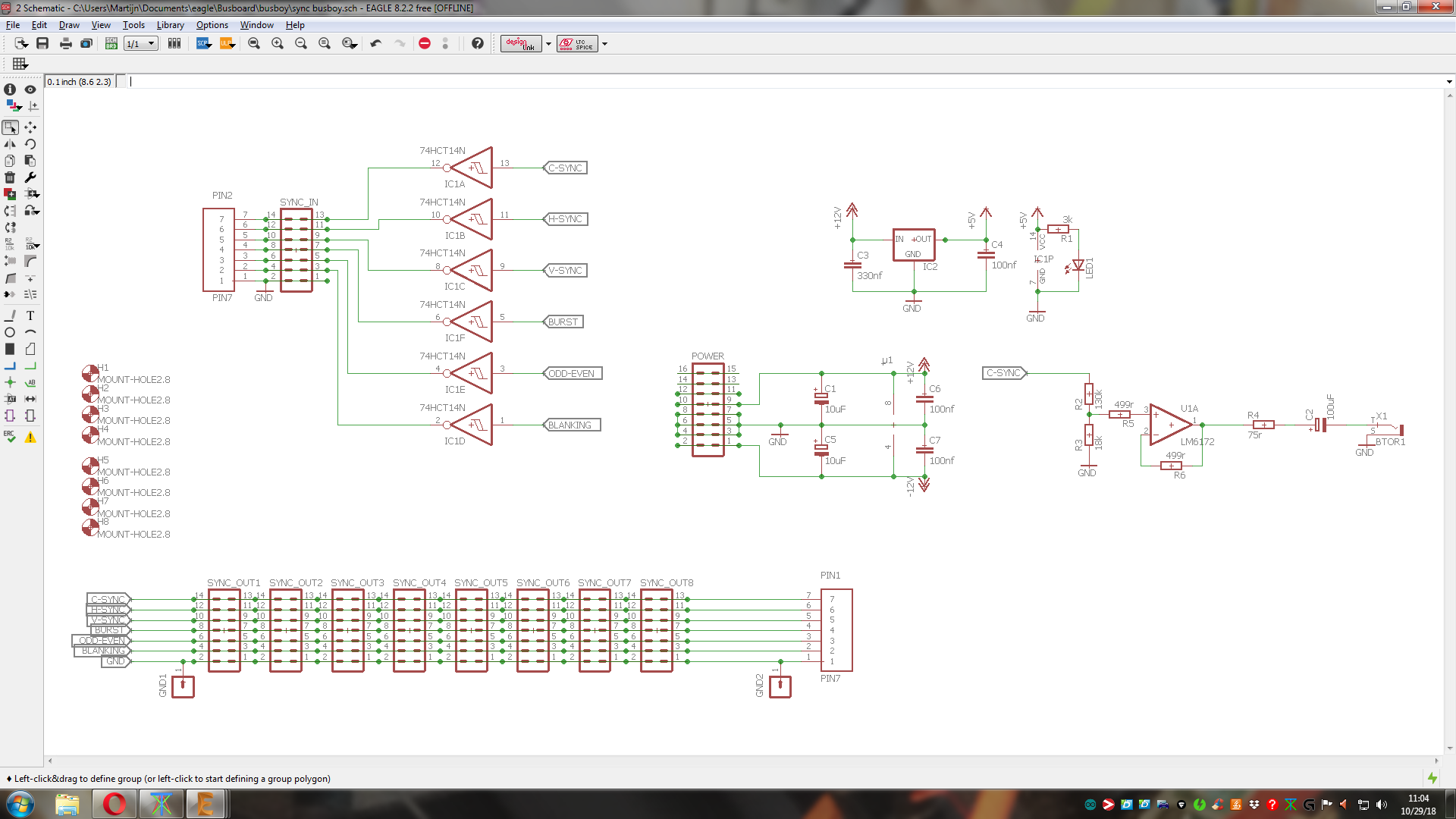
Your HC14 inverters are the wrong way around!
ha, yeah I thought so.
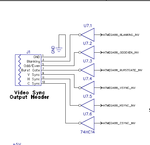
I was working from the C1 schematic.. but there they are positioned this way, because they go to a sync output header  and I got confused
edit:
fixed:
1 Like
Browsing the LZX site product pages to drool over stuff i cannot afford at the moment, i found the
Video Sync Bridge Cable
So i figure this answers my question: i can indeed distribute the bus sync from one case to another directly connecting the pins on the busboard. Now i just need to figure out which pins to connect for this to work.
I’ve found right-angled RCA footprints for Eagle.
So what would be the preference?
vertical or sideways?
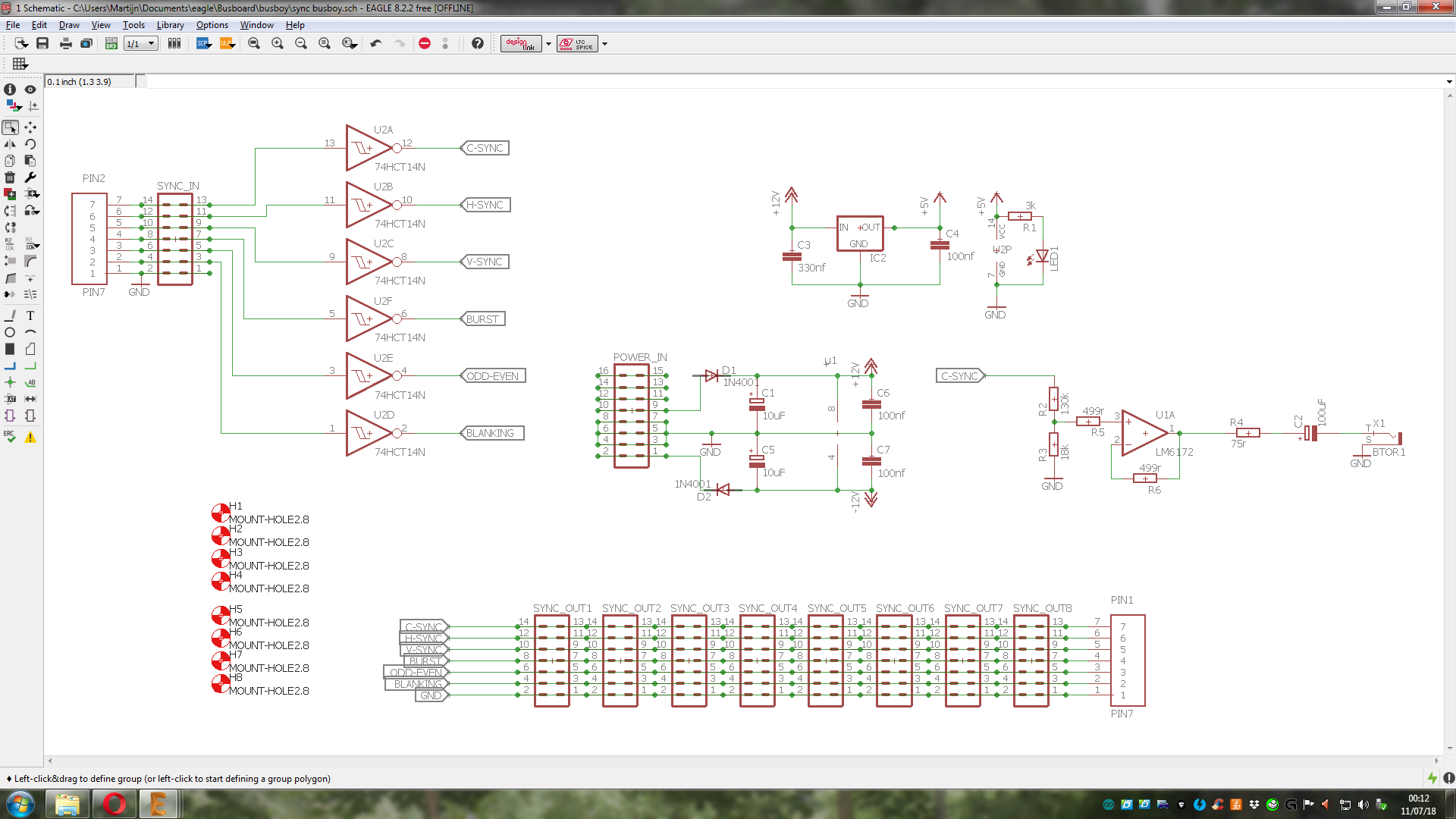
It’s looking good in the last schematic! There are no reverse protection diodes for the power input though (you can use 1n4001 following the cadet circuits.) This isn’t necessarily required, but always good practice.
1 Like
I was wondering if it was nescessary in this case. I’ve added them now.
note: the diodes in the schematic may look weird. but all is ok. there is some very small text that looks like a pin.
1 Like
I’m keeping the vertical RCA socket. makes sense to me and they are cheap.
The hole size for the terminal blocks is now adjusted to a larger value. (it was way too small)
I realized that there is an unused op-amp stage. what useful thing can I add??
1 Like
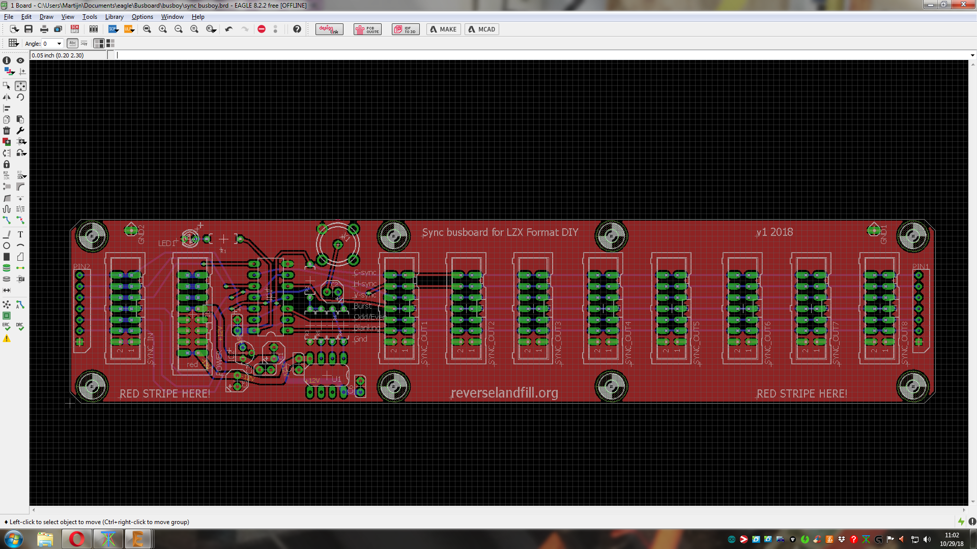
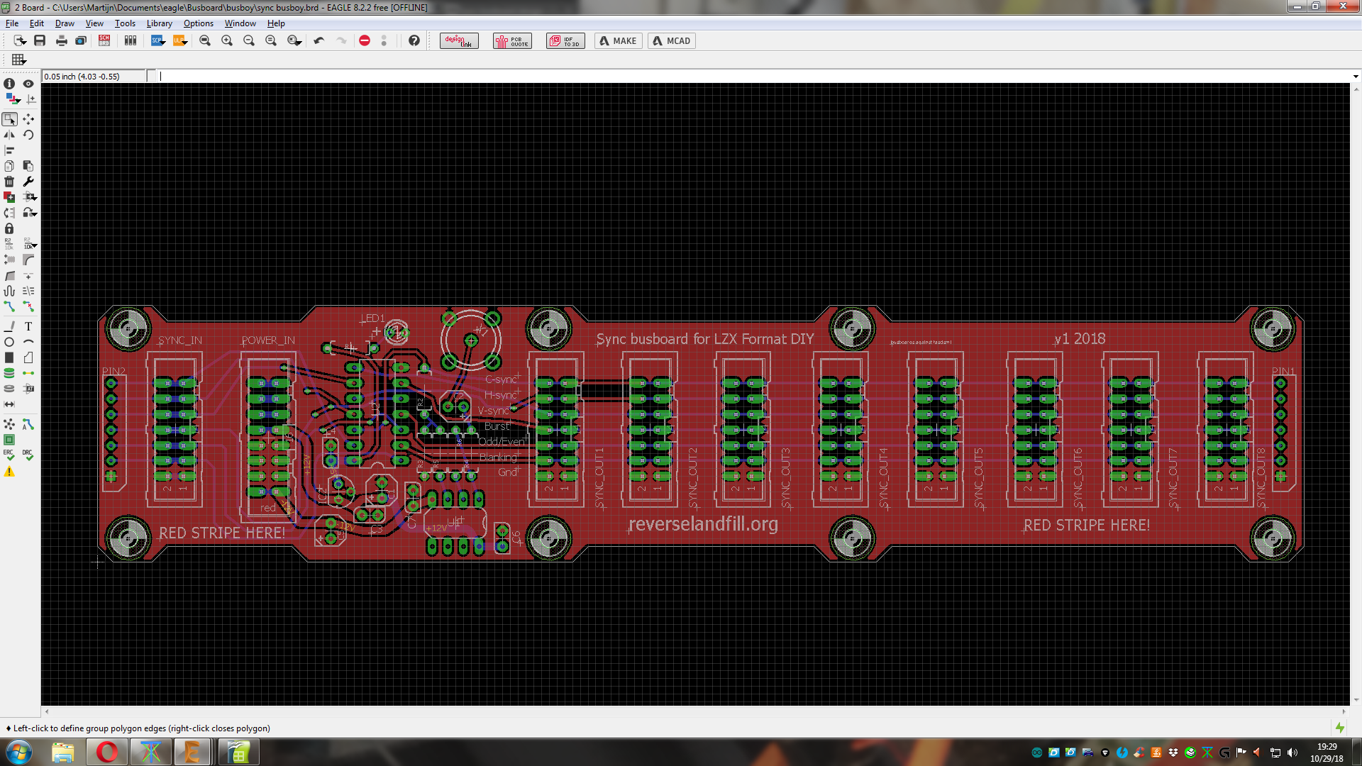
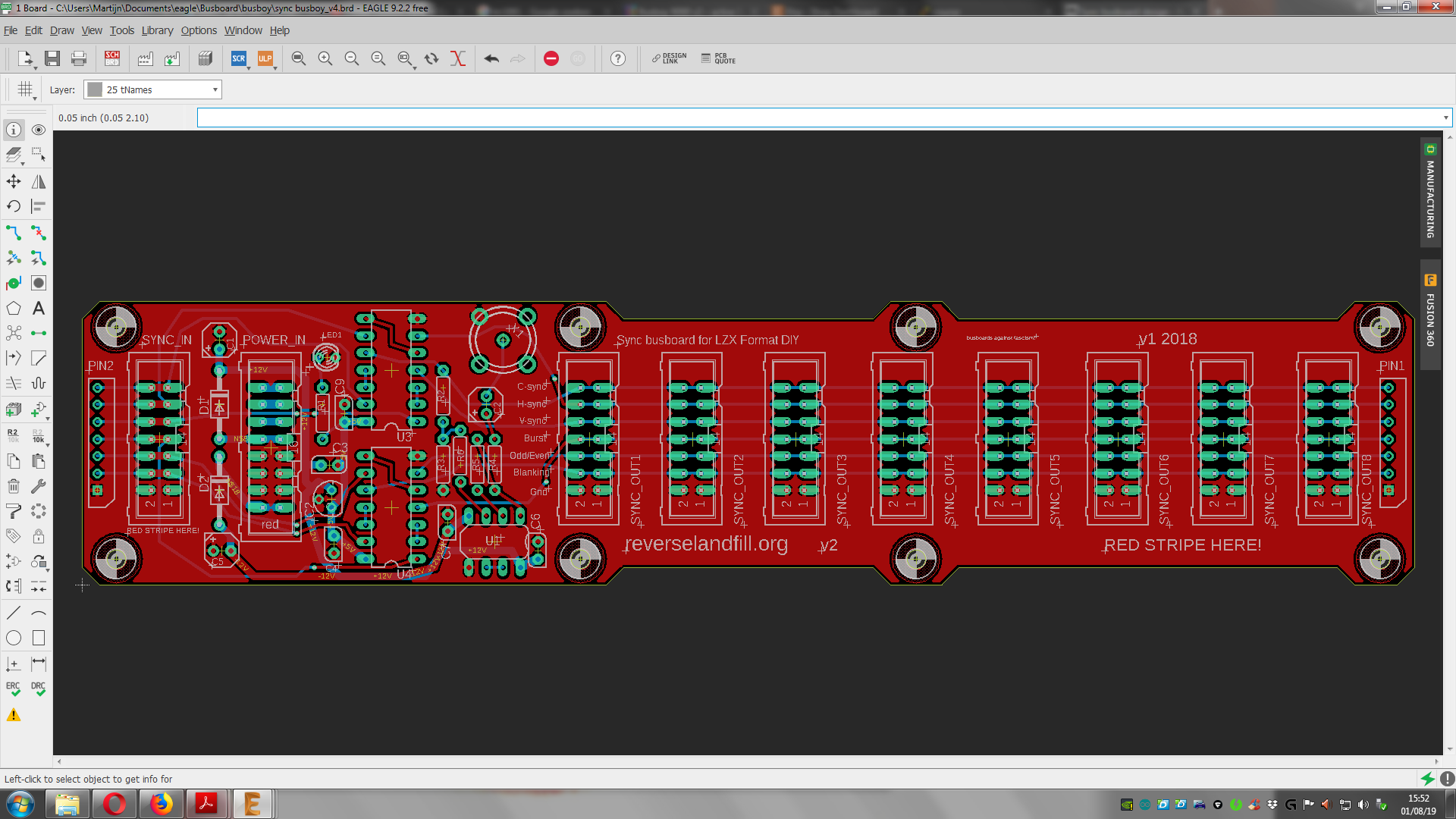
ok, the pcb’s are ordered.
4 Likes
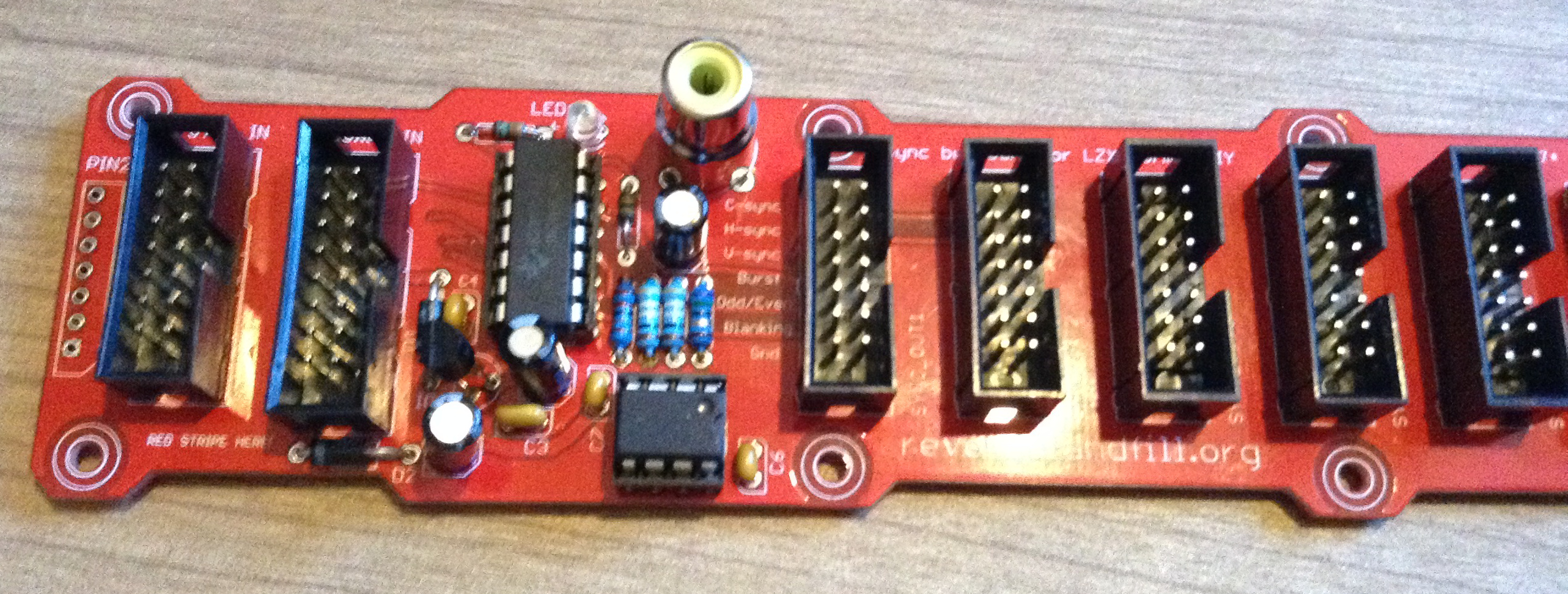
They just came in today! whooo
I’ll test them this weekend. after that, I need someone to test the RCA sync out.
Please PM me if you want to beta test it.
5 Likes
the first one is ready for testing!
5 Likes
testing now:
No correct sync yet. 
signals are coming through, but…
@creatorlars : shouldn’t there be 2 buffer stages to buffer the sync signals?
I think the sync signals are now inverted. (with only 1 inverter stage) so the sync signal is not working.
- I checked this with a scope
when I bypass the 74HC14, it works.
1 Like
Yes there should be two stages. I apologize for neglecting to notice that and point it out. The reason Cortex and Cadet 1 only have a single inverting stages is because I am sending inverting syncs to the buffer, precisely for the reason of removing the need for a second 74HC14. Since syncs are buffered at their source, for your busboard I would suggest that buffering them again isn’t essential. But in a very large system it’s probably a good idea. I haven’t ran into a case yet where the single 74HC14 buffer wasn’t enough to drive any number of modules you want.
Another idea for this busboard would simply be to integrate Cadet 1 into it. So the input is RCA sync and you have some wire header outputs to a passive panel for connecting the 1V sync outputs if desired.
2 Likes
ok, with that confirmed, I’ll make an updated layout.
 time for prototype number 2!
the builder can decide to solder the buffer & RCA output or skip those sections.
I’ll keep you posted!
2 Likes
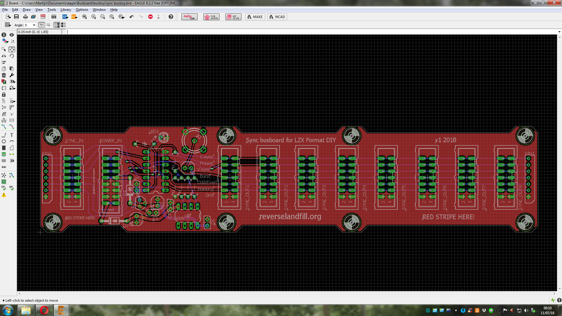
routing was a bit more complex this time. can anyone check if I did ok?
especially the power lines . and the sync signals
I still think I should do something with the 2nd half of the LM6172. Any suggestions?
maybe a 2nd C-SYNC buffer, but without the RCA connector? (because that wouldn’t fit)
1 Like
Maybe just run it to some unpopulated pads as a “DIY/you figure out what to do with it/AUX” C-Sync out? Given that option, I personally would use it to add a BNC connector on a flying lead.
1 Like