is it better to put the C1 cap at the 12v input or use it at the 5v junction?
Are the sync signals of the Castle Clock/ VCO also 1v then?
is it better to put the C1 cap at the 12v input or use it at the 5v junction?
Are the sync signals of the Castle Clock/ VCO also 1v then?
The 10u cap (C1) should be in parallel with C3, on the regulator input.
C2 can be omitted so long as C4 (and the regulator output pin) are directly adjacent to the IC1 power pin.
That’s how I’d do it anyway. 
The CV/Gate bus syncs are always 1V (buffered with video opamps) same as the frontpanel sync outputs, so I’m assuming that’s what Castle will lock to. It probably also works fine being sent the TTL 5V signals too.
this is so cool
I’m so happy to see this community growing
I will always try to patronize community driven output
although I don’t have an 14-pin sync modules currently (I’m using all RCA)
I’m on a roll.
@creatorlars: by “space them out” (the sync traces) , you mean something like this?
So they don’t run parallel to each other?
You shouldn’t need to spread them out like that – I just meant to not group them tighter than necessary. 8-12mil traces, spaced the same as the 2.54mm pin headers pads will be fine! A little crosstalk here is normal and OK, it gets cleaned up by the 74HC14 buffer on the receiving end.
okay!
now I’m thinking about connecting several busboards. there should be a screw terminal on both ends.
The screw terminal blocks that I have here are bigger than the 14pin header pitch, I think you can find ones that are the same as the headers. In that way, you can leave out the buffers on the 2nd pcb and solder a 7pin screw terminal in place of the 1st sync output header. . or maybe I’ll make a separate placement. not sure yet
I think those 14pin IDC connectors have 2.54mm pitch. I’ll check.
My suggestion would be to keep the buffer on the busboard anyway… might as well, it’s cheap, and that way you are rebuffering and distributing on each sync busboard. For very large systems this may be a good idea.
good point.
I’ve added a input header . and a 5v indicator LED. the placement of the power connector is maybe not great
next is finding a way to connect the busboards across cases.
I’m thinking of a panel with 14pin IDC headers (SMD the bottom, TH on top. to prevent pins sticking through the front of the panel)
and then use a flatcable between cases.
or maybe a 7pin plug, like a din cable or so. or a large multipin XLR ? maybe only 6 pins. GND is already there(?)
If you are making the busboard active (buffering, right?) - then why not just add the 14pin sync -> composite/RCA sync circuit? That would make it fit into current systems pretty easily.
Just thinking out loud, IANAEE.
IDK.
I am hesitant because I can’t test this (as I have none of such modules)
and I wanted to make a simple busboard.
but you know. feature creepings.
I’m still not really sure why people would need this, as the RCA modules already use a handy system
But there is something to say for adding it all on 1 board.
If I were to do this, what would be a good amount of RCA connectors?
It might get a bit crowded if I add 8 or more of those.
other musings… if one would use the Cadet sync generator and add a LZX module that needs sync…
It might be handy to have this connection.
I’d guess that one connector for in, and one out would be sufficient were it considered as a case to case connector?
I would also guess you might need a way to select whether sync in came via 14pin IDC connector or RCA jack? (I’d guess not both at the same time would ever be wanted.)
mmh… another good point
Question: Do all LZX sync generator modules have a 14pin output?
as for connecting cases…
I guess most other signals beside the H-sync and V-sync are not needed much?
or can the other signals be extracted again?
I’m trying to make this as DIY friendly as possible. taking into account all possible future DIY modules.
iirc - the sync generators are Cadet I, Visual Cortex, and Memory Palace. C1 and VC both have 14pin sync output… but I don’t know whether MP does.
update.
power header is better like this.
sync in header is moved to the edge of the board.
musings: I’ve routed the sync in signals paths around the power header. Does it matter … or can I just route them between the power pins . I was thinking of interference…
to do:
measure the screw terminals again.
add funky graphix. I have some ideas already 
#done# the pcb holes are now symmetrical
question: how does the 74HC14 buffering work? I would not have thought to use these IC’s this way. they look “backward”?
ethernet or HDMI offer a lot of connections and easily available cables as well but it sounds like you’ve got things sorted
that might be a good direction.
And I guess the cables can be a bit thinner, as the signal gets rebuffered on each busboard.
something with a good steady plug with some locking mechanism and a round cable would be optimal in my opinion.
RCA in this board will be useful in the case of a system without VC, like mine.
It will be useful to drive Cadets IV or IX from a MP or sync a Prismatic Ray or other Expedition form a Cadet I Sync Generator.
Although, this can also be built into a little module, ‘sync distributor’ or smt. and be independent from the sync busboard itself.
Very interested thread indeed.
based on this:
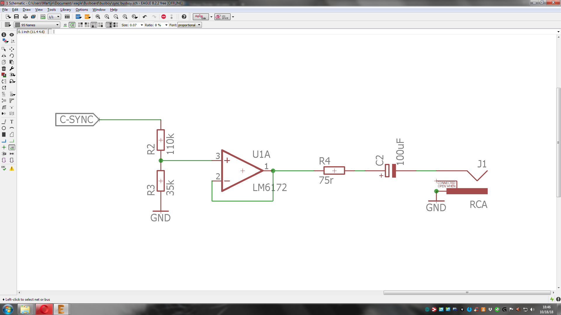
If you want RCA sync output from your Cadet 1, you need to attenuate the CSYNC signal to ~0.6Vpp (2X gain), buffer it with a video op-amp (LM6172) and drive it thru a 75 ohm output resistor and large AC coupling cap to the RCA jack.
something like this?
output voltage is now 1.207. (2x 0.6) or should it be 0.6 in total?
If I were to add this, we need to do a prototype test. beta testers would need to check several scenarios.
(maybe this is overkill and I’m being overtly careful. want to do it right. and not destroy expensive modules ![]()
@reverselandfill The circuit is looking correct, however LM6172 needs 499R input resistor (insert in node between R3/R2 and U1 pin 3) and needs to see some resistance in the feedback loop (add 499R or 1K resistor between U1 pins 2 and 1.)
For driver amplitude you want 0.6V total (standard video sync amplitude is 0.3V, so we want to drive at double that amplitude – when it is terminated by 75 ohm on the other end, the 0.3V amplitude is restored.) Essentially you’re creating a valid video signal here, where video is just black, but can be received by a display or any video device with a sync/genlock input.
Regarding RCA sync to 14-pin sync, there is not really a better or cheaper or easier way to do this than the Cadet I circuit, so unless you want to integrate Cadet 1’s PLL and MCU components into the busboard design, I wouldn’t recommend it. The other way around (14-pin sync to RCA sync) is easy with the opamp buffer as shown.
The original Video Sync Generator, Cadet I Sync Generator (which is a simplified version of it) and Visual Cortex all provide 14-pin sync output.
Memory Palace and Vidiot (two other master sync generators for an LZX system) provide only the RCA sync output. However in these use cases, they are not really “master sync” modules, since they do not provide frontpanel sync outputs – systems using these as their master sync source can be though of more as “Memory Palace + expander modules” rather than Visual Cortex or Cadet 1, which form the basis for a holistic system (as we’ve imagined it, anyway.)
As far as connecting sync between cases, I would recommend including a slaved sync generator (Cadet 1) in the second case as opposed to trying to connect the 14-pin connections through some sort of DIN cable or similar. This way the cable can be as long as it needs to be, uses simple parts, and you don’t risk any weird connector or cable length related crosstalk issues.
We moved to RCA sync I/O on all production modules starting with Visual Cortex, because this is already an established standard (Genlock in/out on broadcast devices!)
We’ve stayed with the 14-pin connector on DIY modules because… well, the goal of these modules is to teach people how video circuits work, and having access to them all as TTL signals on a ribbon makes it easier to tinker and expand!
Visual Cortex provides the 14-pin sync outs to support Cadet and legacy formats, so we recommend including this module in your system if you want both worlds. I do see some merit of the RCA sync output on the busboard, so that people with DIY systems can add production modules to their rigs without requiring anything else.