BOM and Build Guide
Click for BOM:
| Qty | Value | Parts |
|---|---|---|
| 25 | 1K | R5, R6, R7, R8, R9, R13, R18, R19, R23, R25, R26, R28, R29, R30, R31, R32, R33, R34, R35, R36, R37, R38, R39, R40, R41 |
| 14 | 100n | C1, C3, C4, C5, C7, C8, C9, C10, C11, C12, C13, C14, C16, C17 |
| 7 | 499R | R2, R3, R15, R16, R20, R21, R46 |
| 7 | LM6172 | IC1, IC2, IC3, IC4, IC5, IC6, IC7 |
| 6 | 100K | R1, R4, R14, R17, R24, R27 |
| 6 | 1N5711 | D3, D4, D5, D6, D7, D8 |
| 4 | 4.99K | R10A, R11, R12, R22A |
| 4 | PJ302M | LAYER1, LAYER2, LAYER3, OUT |
| 2 | 10u/25v | C2, C6 |
| 2 | 1N4001 | D1, D2 |
| 2 | 68R Ferrite Bead | FB1, FB2 |
| 2 | B10K - T18 shaft | VR1, VR2 |
| 1 | 2x5 (10-Pin) male header | J9 |
| 1 | Pcb set | - |
| 1 | 10-16 Pin Power Ribbon | - |
| 2 | Davies Knobs T18 (transparent recommended) | - |
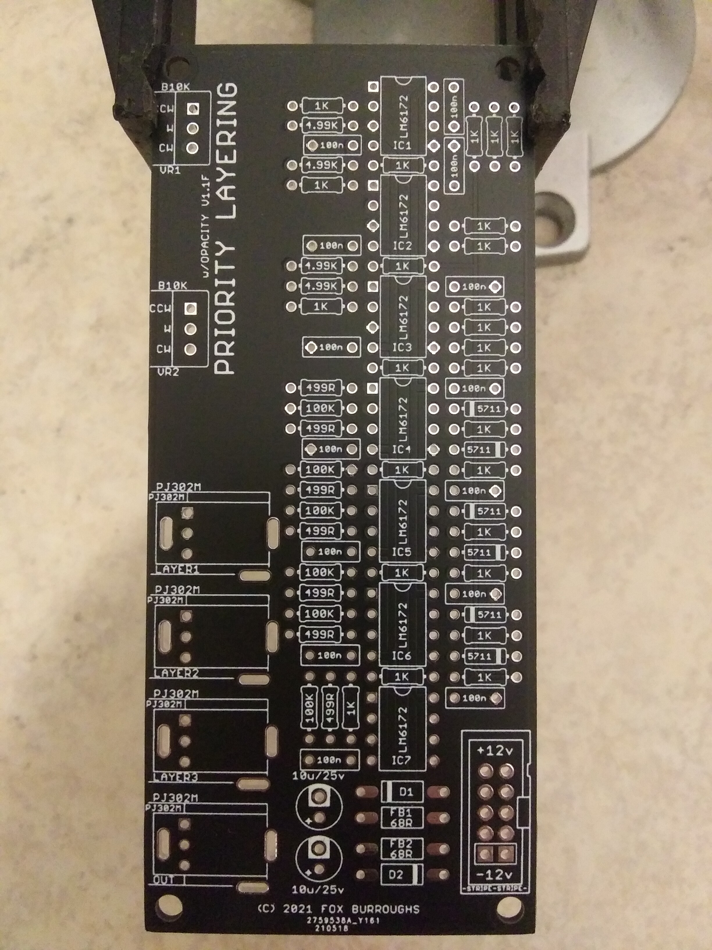
Click for Build Guide:
Step 0.
Using a PCB vice will improve your DIY experience immensely.
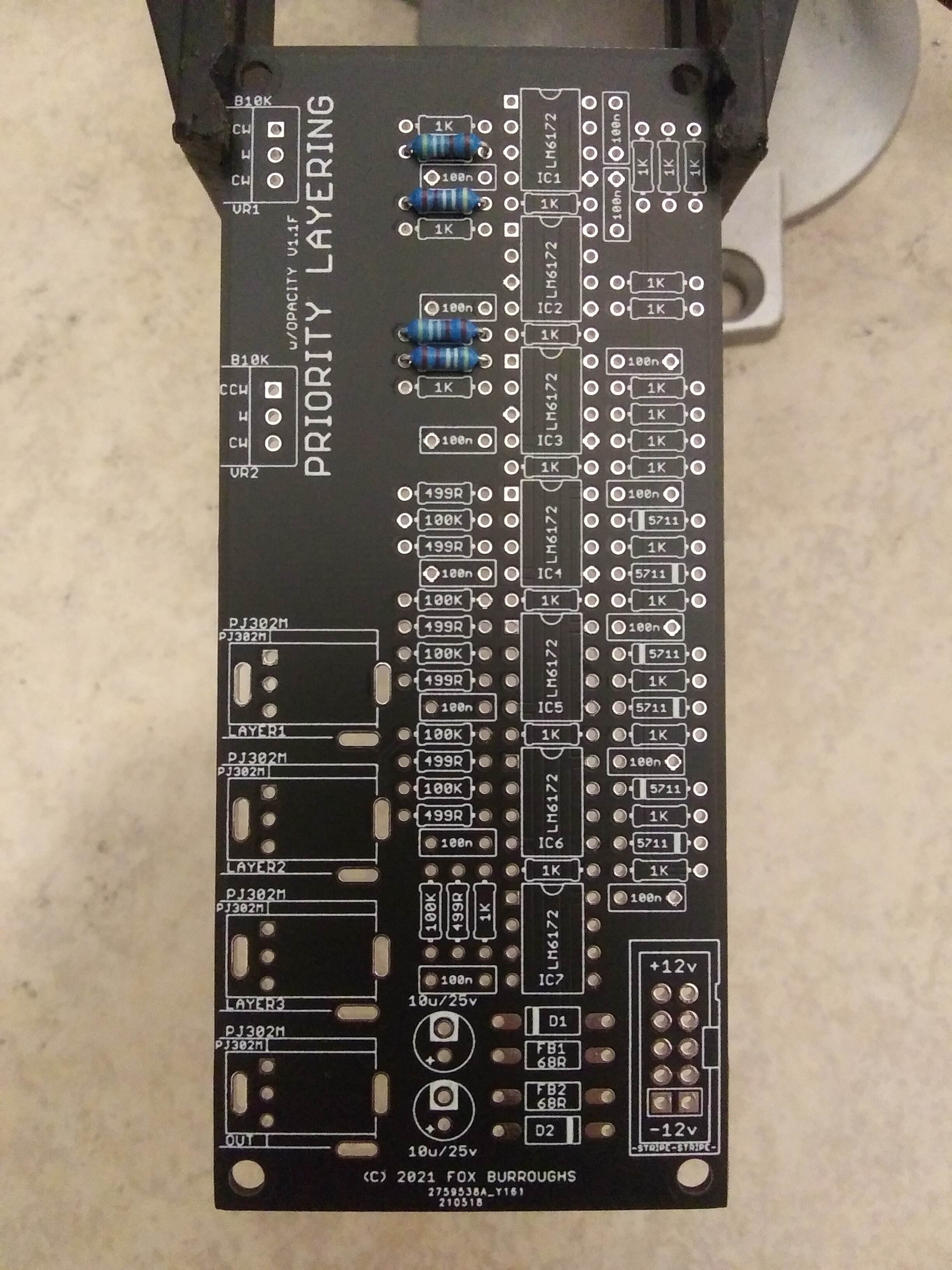
Step 1.
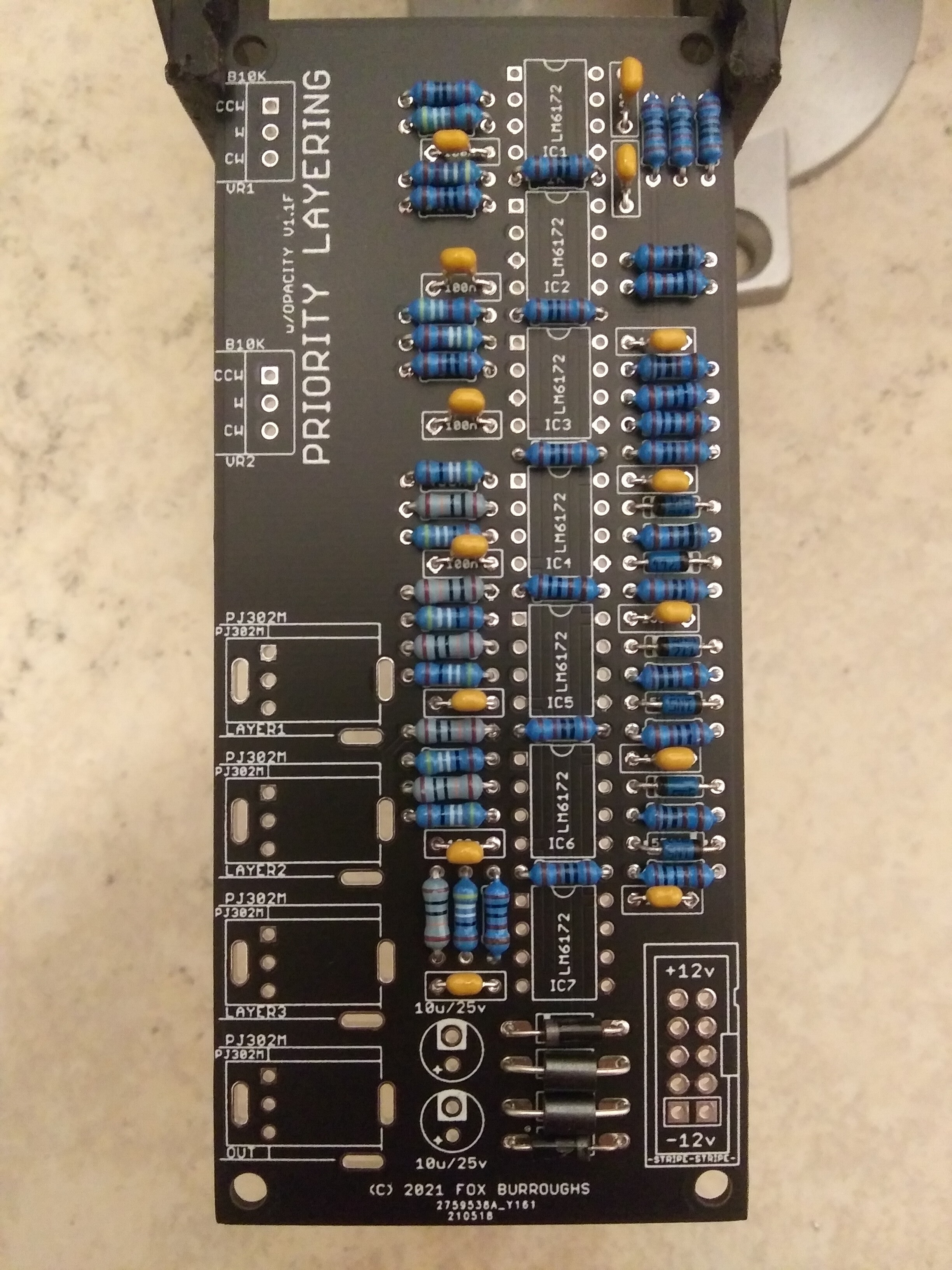
4.99K ohm resistors.
Step 2.
499 Ohm (499R) resistors.
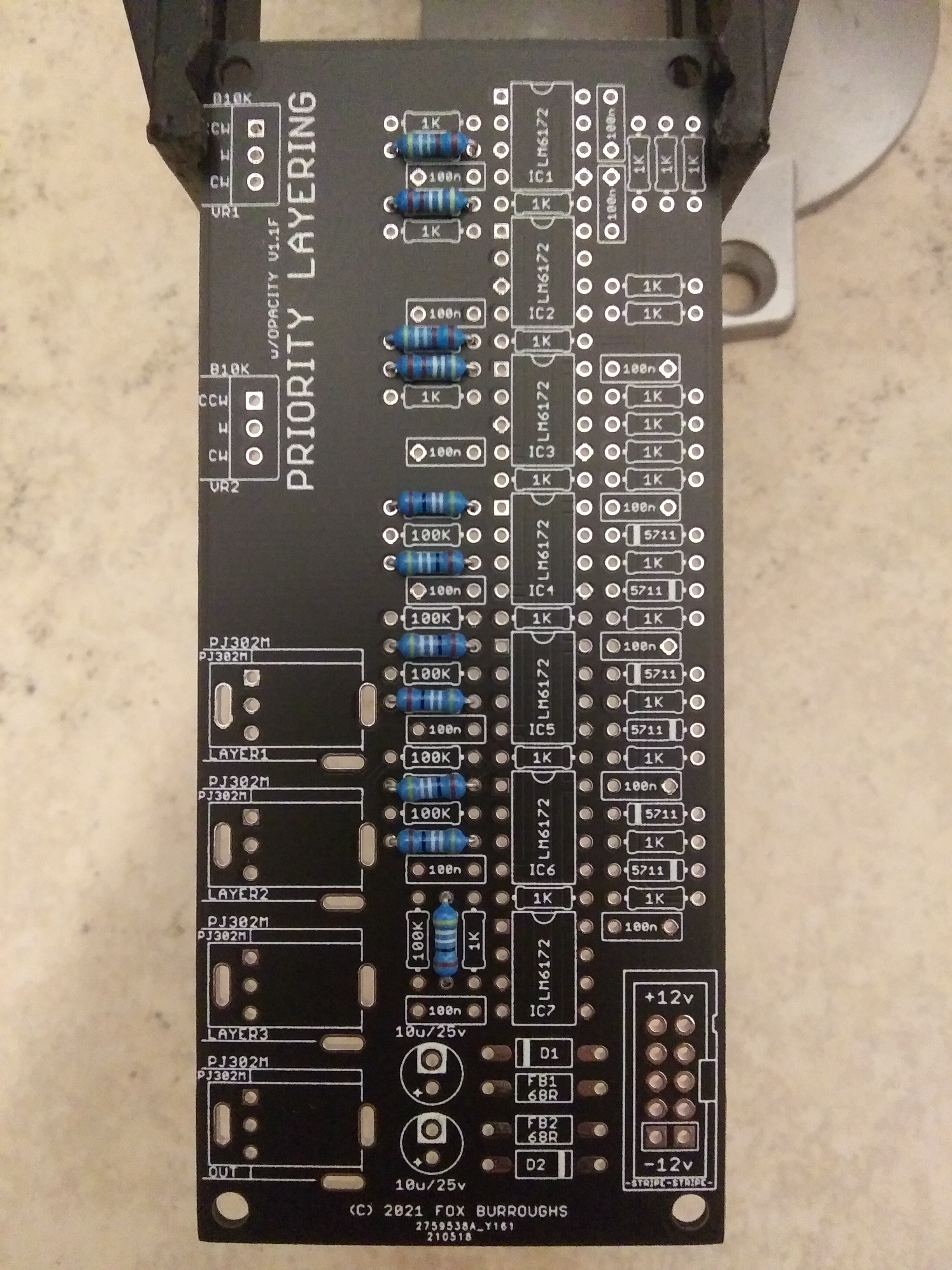
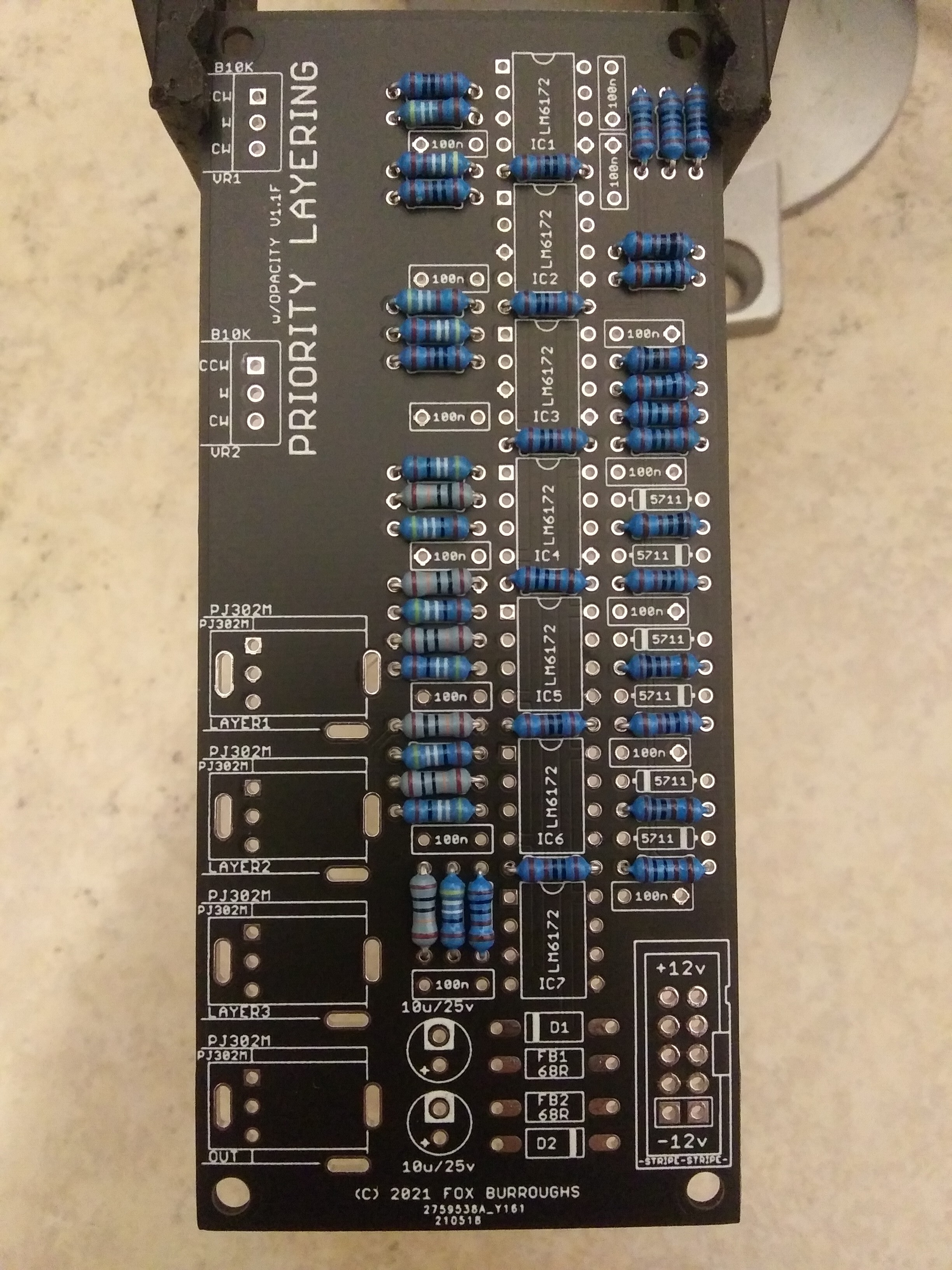
Step 3.
100K resistors.
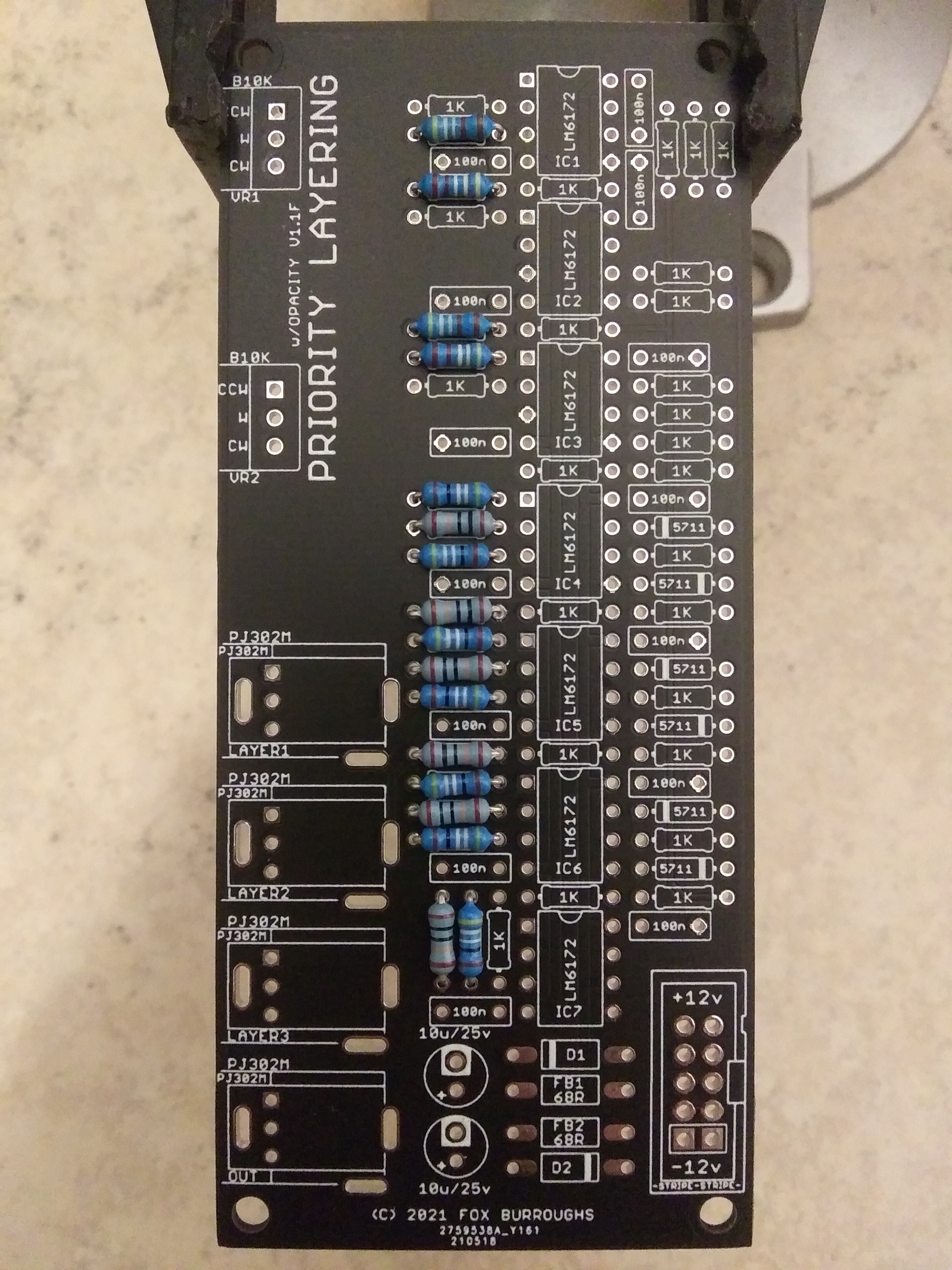
Step 4.
1K resistors. There are 25 of these, so this is the most tedious step.
Step 5.
1N5711 diodes. Diodes are polarized, so the orientation is important. Take special note of the black stripe on each diode and line it up with the silkscreen’s stripe for all 6 of these.
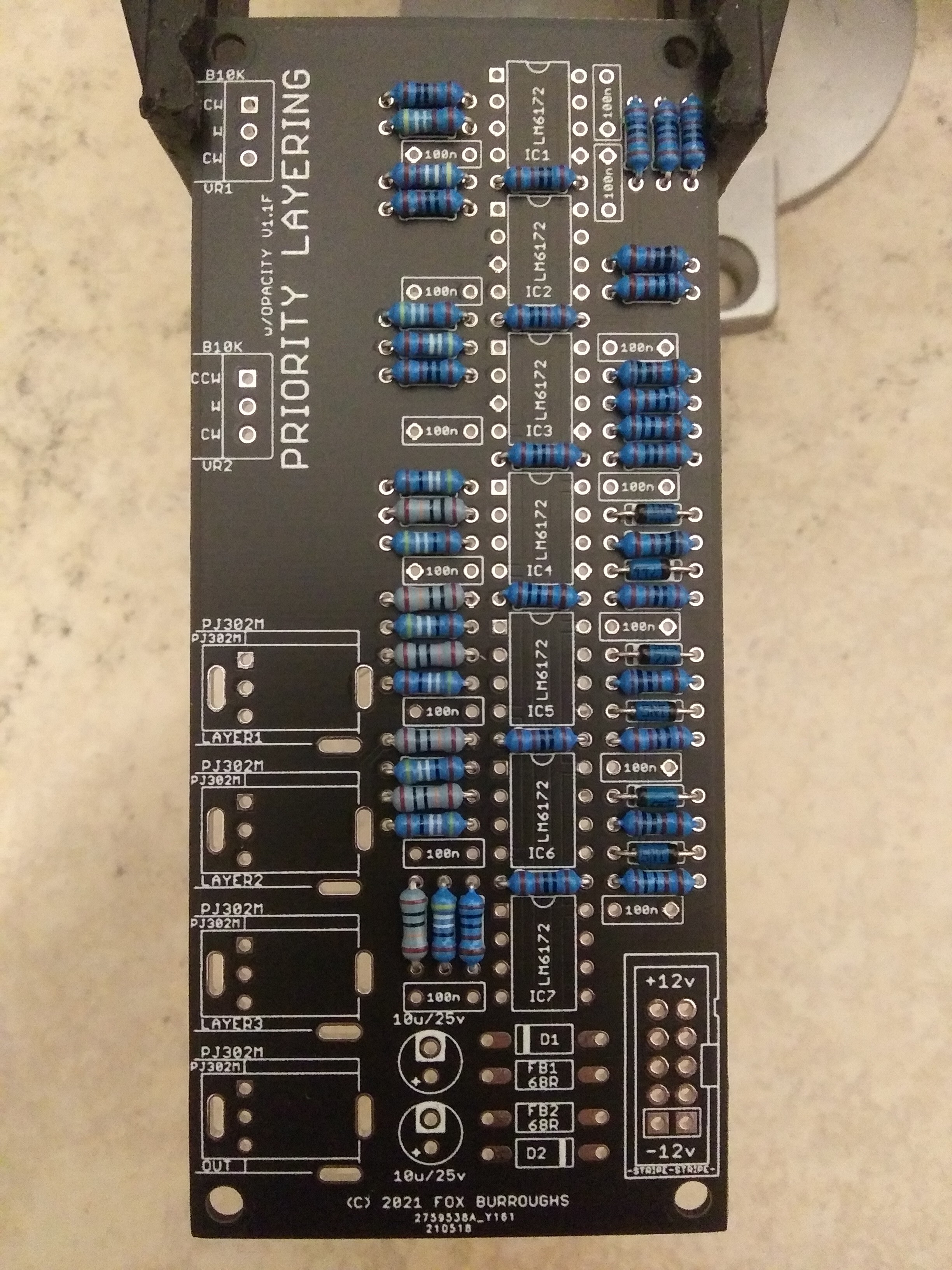
Step 6.
Protection diodes and Ferrite Beads. As with the step above, diodes are polarized.
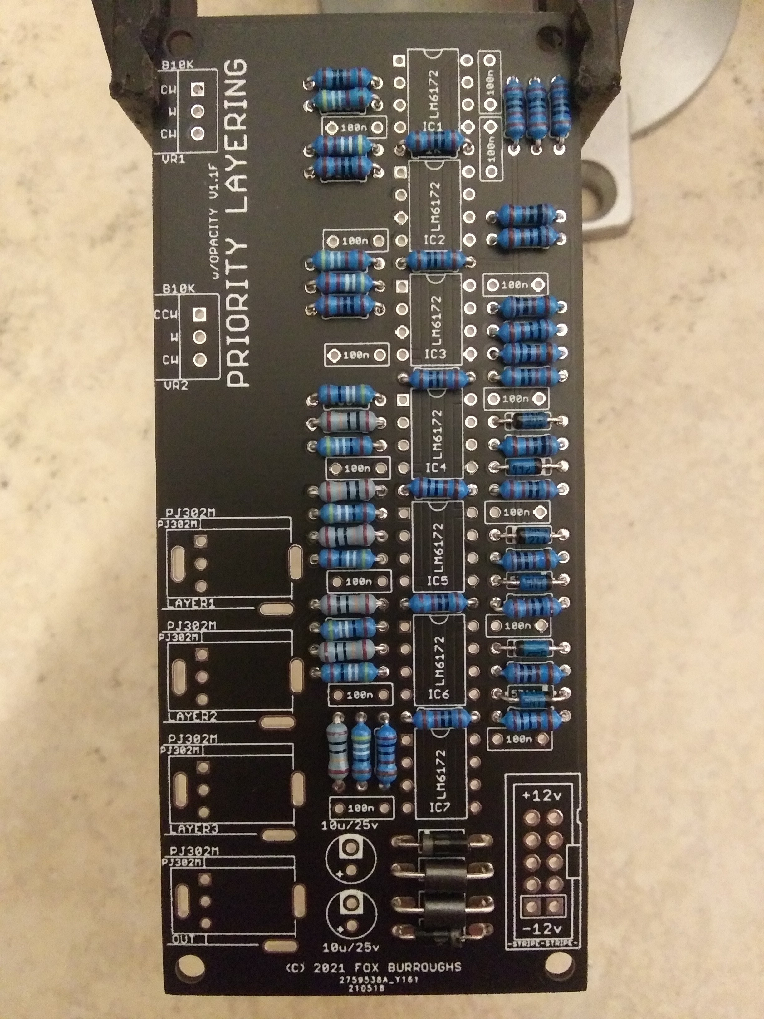
Step 7.
100nF Ceramic Capacitors. There are 14 caps positioned next to the supply pins of each IC.
Step 8.
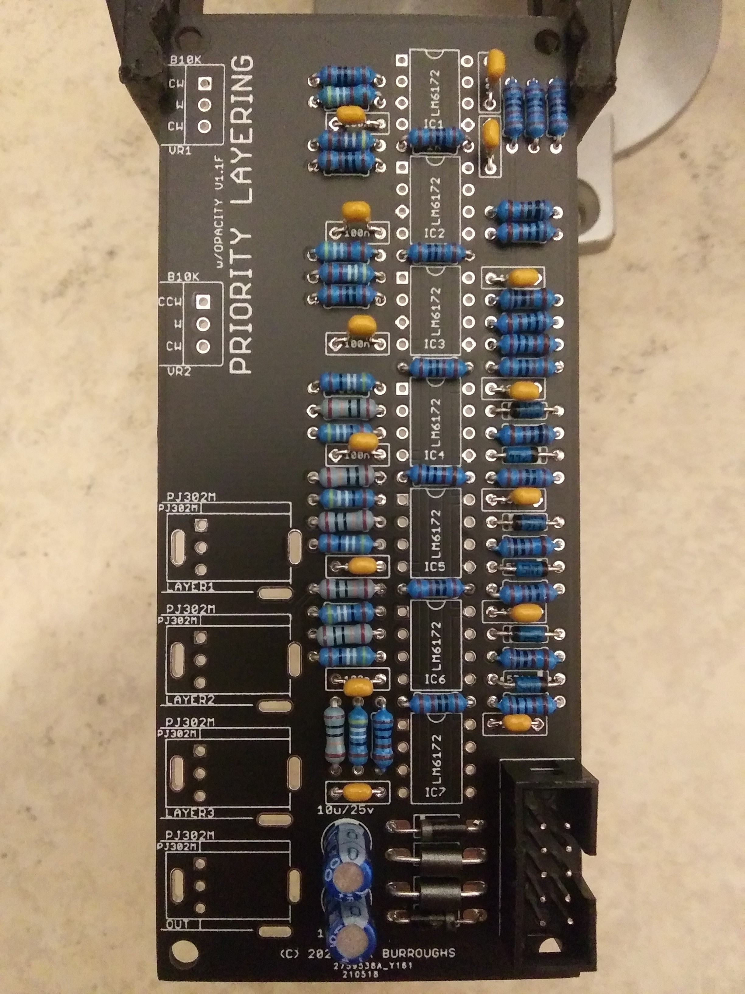
10uF electrolytic capacitors and power connector. Unlike the 100nF caps, these ones are polarized. Take note of the stipe on both caps illustrating the negative lead.
Also important is the “key” or “notch” on your power connector. This points outward from the board as pictured below.
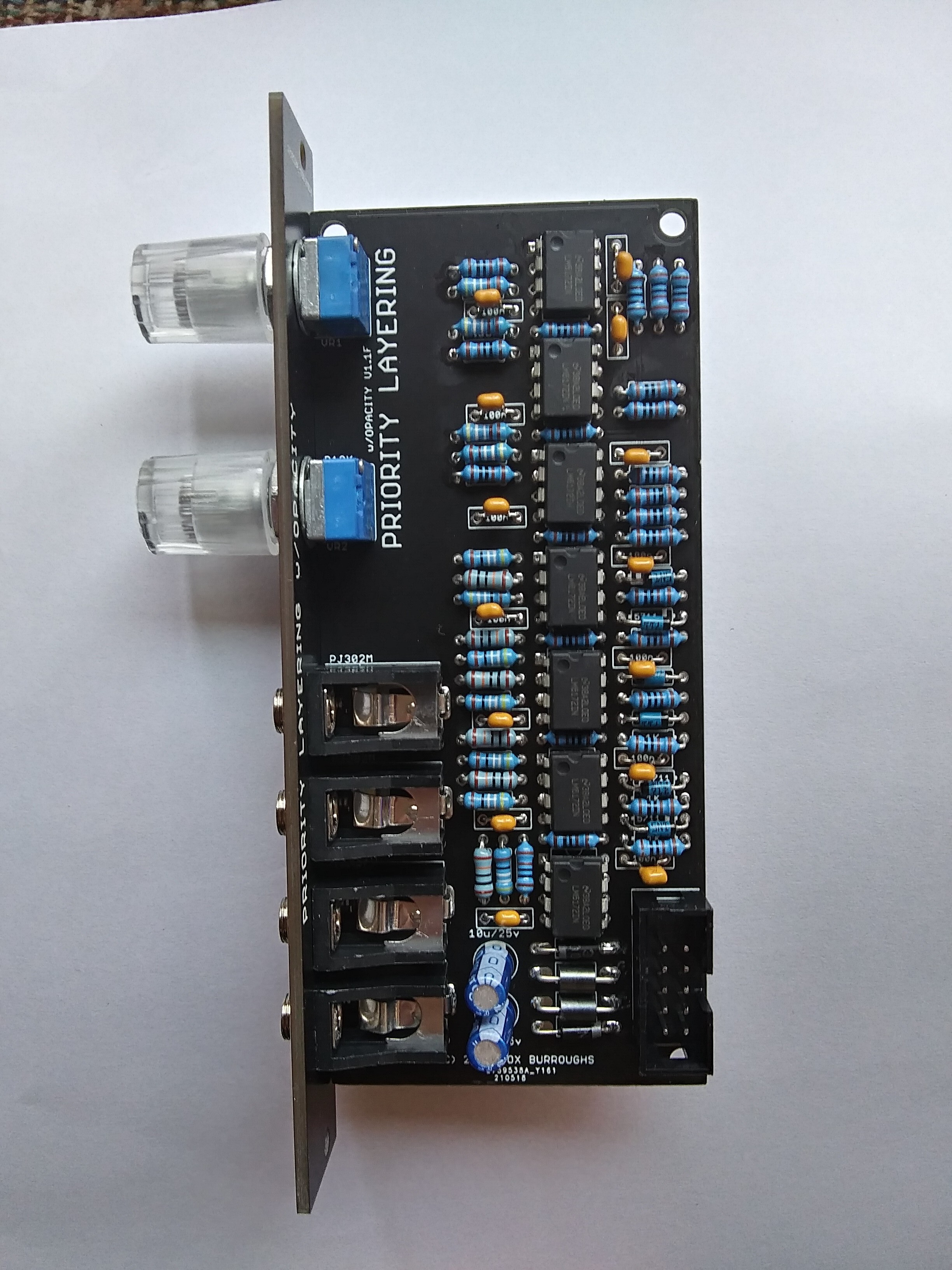
Part 9.
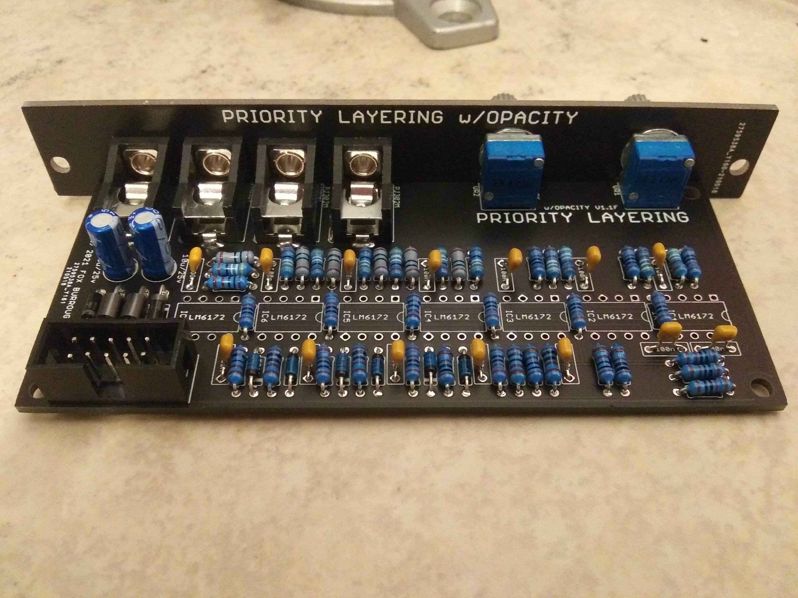
Jacks and pots. Place each of these components into the board and install the faceplate. Gently finger-tighten each nut to the jacks and pots before soldering. This ensures that each one is lined up with the faceplate before they are fixed in place.
Gently flip the board over and solder them in place.
Step 10.
LM6172’s. I prefer to solder my IC’s last as they expensive and may be more sensitive to heat than passive components.
Now that the soldering is finished, I choose to remove the faceplate and clean any excess solder flux away with plenty isopropyl alcohol and a toothbrush. It is also a good time to visually inspect your solder joints.
Afterward, you may finally reinstall the faceplate, fully tighten the nuts in place and install your knobs.
Enjoy!