Really cool idea, that would be useful for prototyping for sure!
About composite, the IO setup is quite straightforward (75ohm to ground with op-amp buffer for input, 2x gain op-amp with 75ohm in serie for the output), a nice addition would be a sync extractor as LM1881 or LMH1980, but depends of the space, and can also be soldered to the “veroboard” area if needed.
2 Likes


Additional idea: instead of a breadboard interface , why not some headers? Then we can non destructively bus various circuits using the same PCB idea you are making. Would be great for fast prototyping of a few ideas at once 
1 Like
all the ‘breadboard’ pads are on a standard header grid, so it is up to the user to make use of that.
My main purpose is that I want to make semi permanent prototypes, where the ‘semi’ part can be the connections to certain pots and jacks and the buffer stages
all my products are open source, so you can also make your own variations.
2 Likes
Thanks again for your open source work
1 Like
newest updated design, layout in progress.
If you see any obvious flaws (schematic related) please tell me!
I’m ordering this one first, then see what features could be better for smaller versions!
Bigger soldering area, wider pcb. power options expanded
3 aux pots, aux 4 jacks, 2x buffered video in, 2x buffered out

big schematic file:

5 Likes
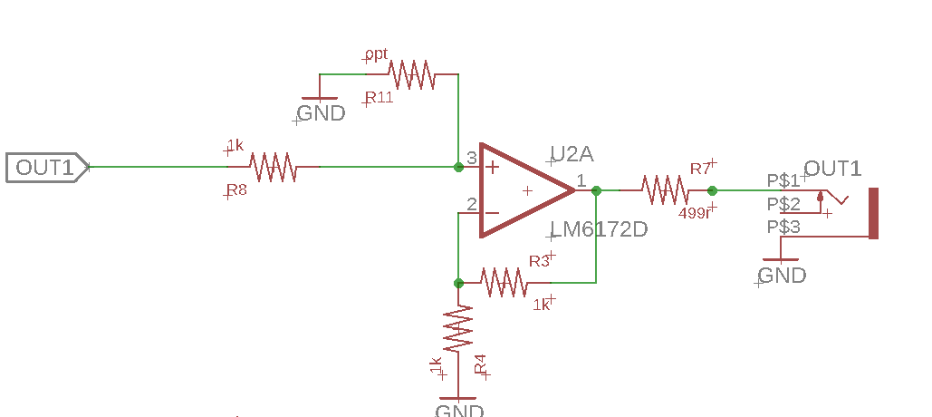
On the ouput op-amps I suggest an optional resistor to ground from the +in pin, so it could be configured as a voltage divider if required.
All those thin parallel bottom layer traces might lead to signal crosstalk and stray capacitance… maybe it would be better to try to reduce the trace lengths if you can, even if it means the connection points are distributed around the board rather than all together… Video-rate electronics can be pretty tough 
Also, having -5V regulation as well as +5V would open up possibilities for some of the non-12V capable op-amps and other chips. Some of those are SMD and smaller footprint, though.
1 Like
thanks for the detailed tips!
I’ll try to reduce the length and parallel lines.
routing is a bit of a pain, with those headers all on one side.
-5v is a good idea, I’ll add it!
for now, I leave it at through hole. maybe with next version we can try SMD parts
I just want to start using this board as quick as possible, then see what can be updated in the future
voltage divider thingy: like this? My mind if all lines now, so I can’t think…
1 Like
Yes, perfect. You can do almost anything with an op-amp like that, boost or cut! (let’s not think about inverting )
The scaling formula is: OUT = IN x CUT x BOOST
Where CUT = R11 / (R8 + R11) and BOOST = R4 / (R3 + R4)
Since we normally keep R3 constant at 1K, that means the boost is mostly a factor of R4. For the cut, any reasonable middle-of-the-road values for R8 and R11 will be fine.
My advice is to just get it made up. You’ll work out what needs tweaking soon enough once you’re using it. There will always be another better version
2 Likes
smaller headers, -5v , shuffled parts around. almost ready to go!
one thing I wanted to do is add composite RCA footprints. have to look for those. does anyone has the right angled ones LZX uses on the Cadet?
maybe I will exchange the 10pin powerheader for a 16pin, to have sync lines…

1 Like
RCJ-044 Footprint
https://www.cuidevices.com/product/resource/pcbfootprint/rcj-044
1 Like
Heh, you just beat me to it
1 Like
I was expecting the same to happen to me 
Got to love the Internet for speed of info gathering.
This will be the limit of my ability to help with technical stuff but every little bit counts I guess.
1 Like
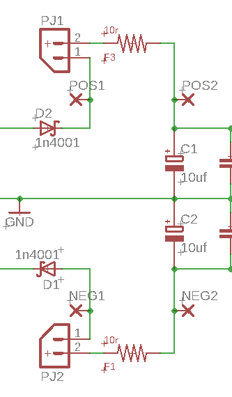
I thought of something else! Might be a bit left-field but how about a break in each of the incoming power lines from the euro power connector, with a pin header you normally jumper across but which you can remove when you want to use your multimeter leads to measure power consumption? If you don’t want it you can just solder a wire across it.
1 Like
There are plenty of non-right angled RCA connectors you could use if you wanted to keep consistency with your other sockets and pots, by the way.
1 Like
yes, that is a good idea. still need one of those - a RCA vertical footprint, like the one on @syntonie CBV001 (I have one that I used on the syncbus, but it is a bit uncommon I think)
updated version with sync

1 Like
I have to see what I do with that. some jumper solution maybe
or the ferrites
1 Like
Using the ferrites is a great idea! Good thinking
this looks workable. jumper inserted = power goes through ferrite, no jumper = you can measure the mA use via the pos1 & pos2 pads, neg1 & neg2 pads for the negative side.

1 Like
