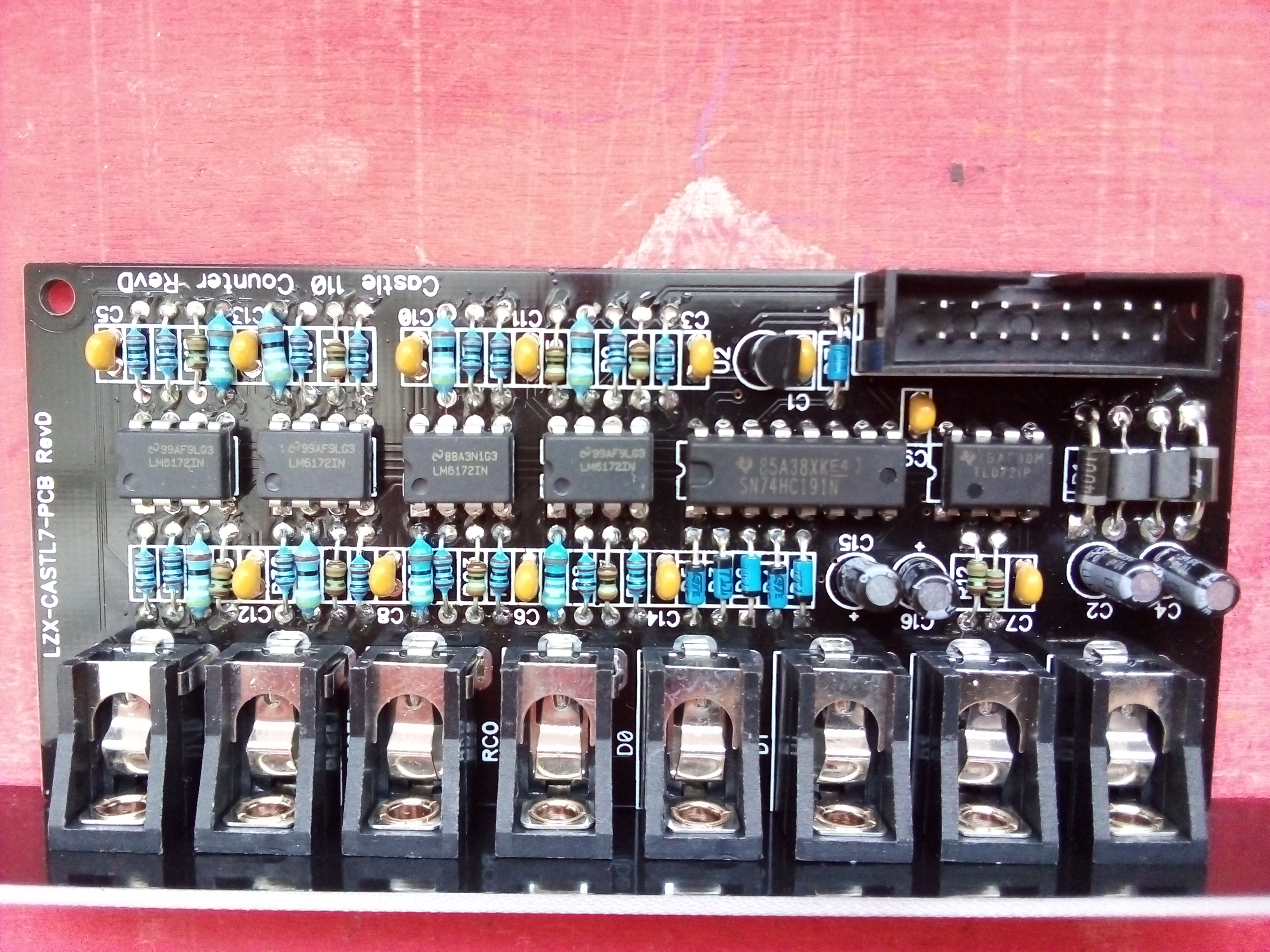
Hello, I’ve finished building a Castle 110 Counter (LZX-CASTL7-PCB RevD) but on powering it up, my whole system wouldn’t switch on until I plugged it out 
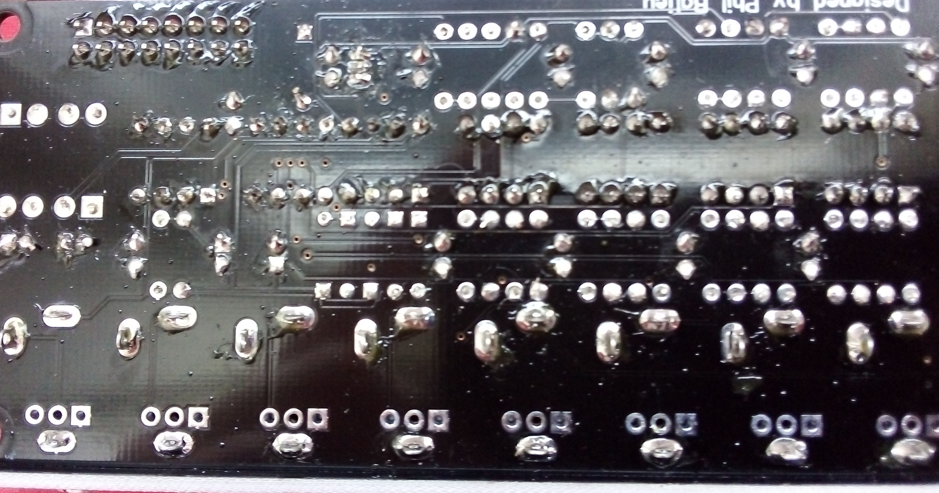
I’ve given it a thorough look over: no ICs, diodes, or polarised caps in the wrong way but amazingly, I can’t see the trace for the C2 cap that can be clearly seen on a couple of the other Castle PCBs I have here. (Update: its on the bottom  I’m an total noob at circuit diagnosis)
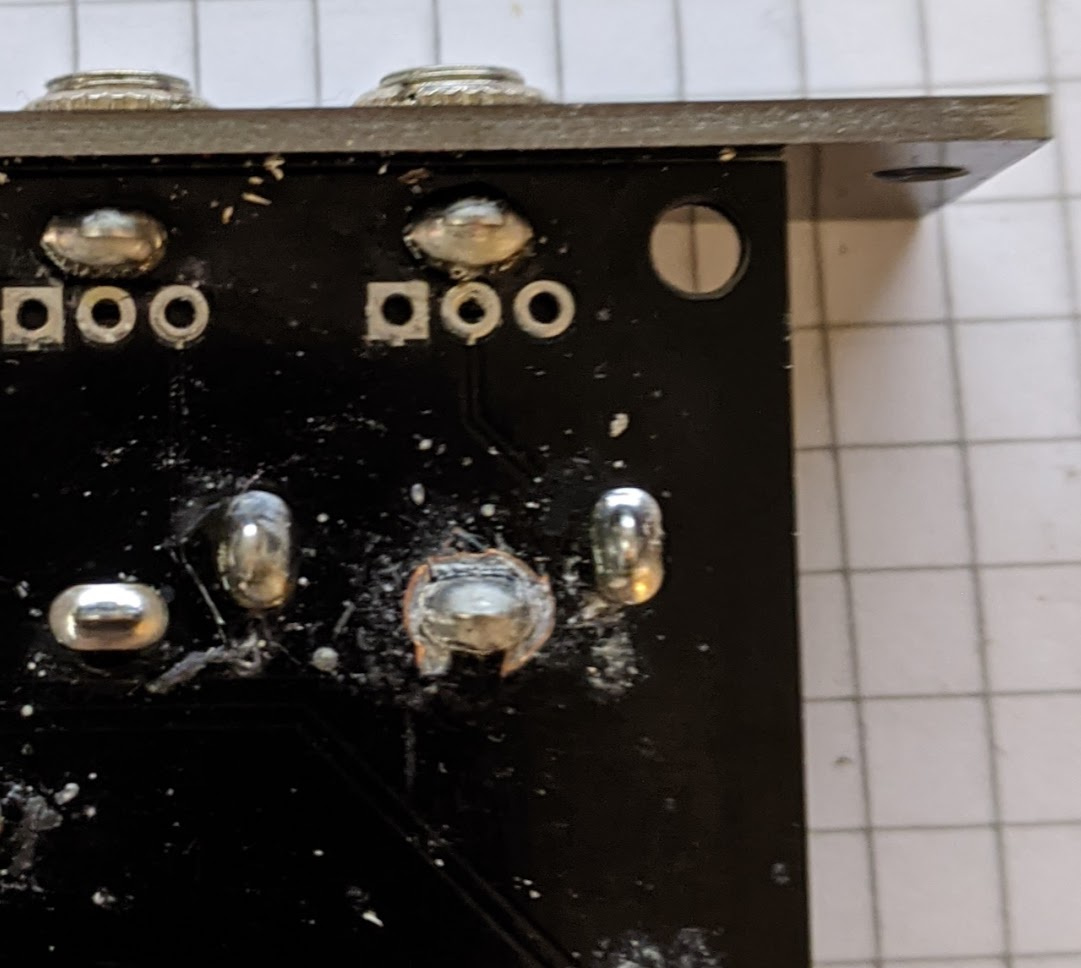
I’ll take a couple of photos, any help would be greatly appreciated. I’ve got a basic multimeter and a slightly wonky oscilloscope but I’m a total novice with them.
I’ll tag a few of you techie regulars on here & untag you if you consider this unnecessary or a nuisance. Apologies in advance. Also thanks for any tips or help offer 
@reverselandfill @transistorcat @Fox @VanTa @VisibleSignals @syntonie
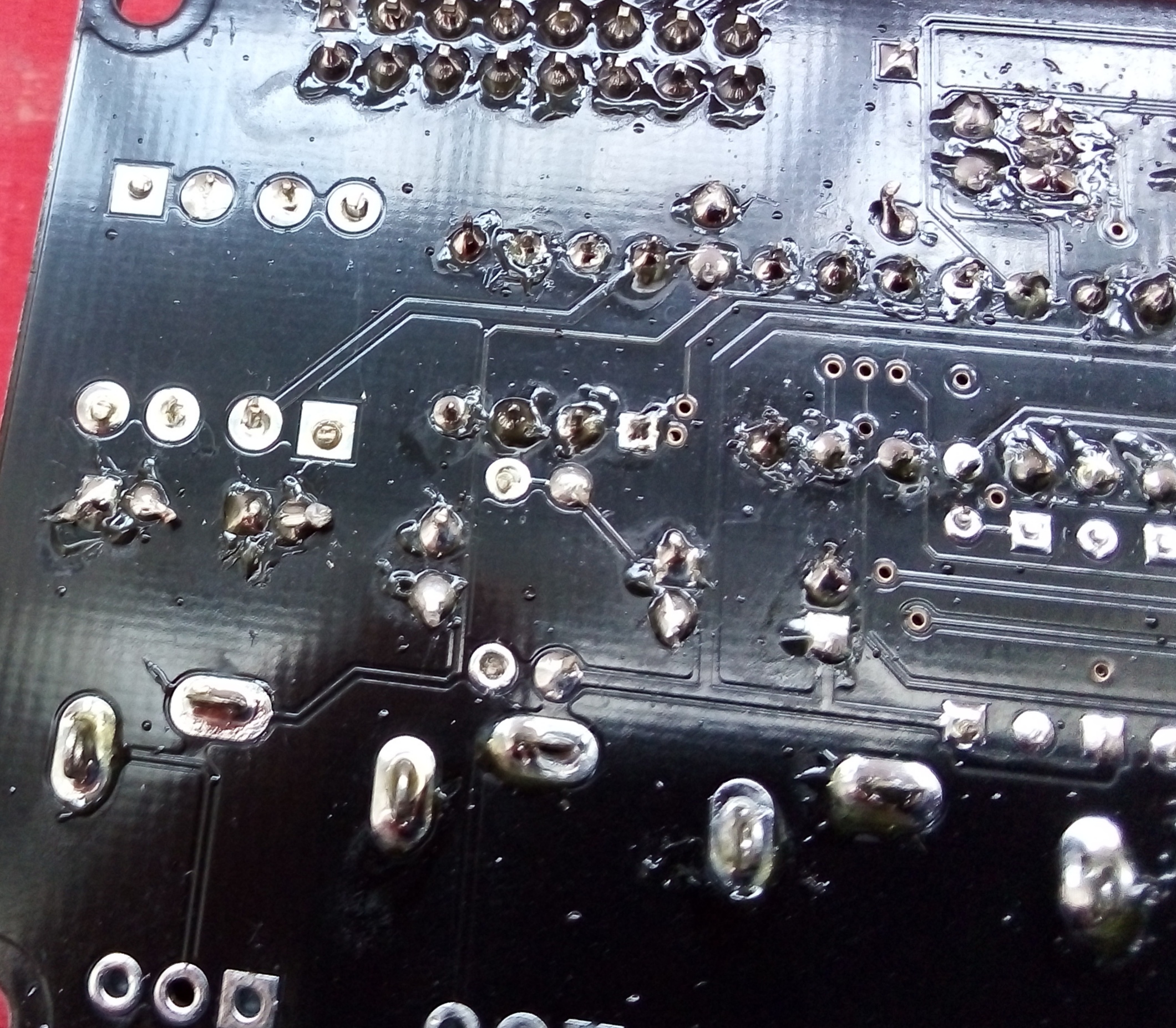
I got the impression while soldering some castles that the tolerances between the solder lands and the copper fill were a bit tight.
I had a board where one (admittedly over-tinned) pad was shorted to ground that i had to carefully cut free to get the module working.
First things first: try to measure the resistance between V+, V- and GND. All three combinations of pairs, remember to measure your probes/offset by just touching the probes together.
If you have the same problem, i expect you’ll find one of these three pairs will measure close to zero.
If you have access to a good typically bench-top multimeter that will let you measure down into the milliohms you can use that to zero in on the fault, but this will not really work with a common meter 
If V+ or V- is shorted to ground, i’d inspect all the pads that should tie to that net on both sides, and try to very carefully make a cut between the pad and plane with a scalpel or other sharp knife (make sure not to cut the intended trace)
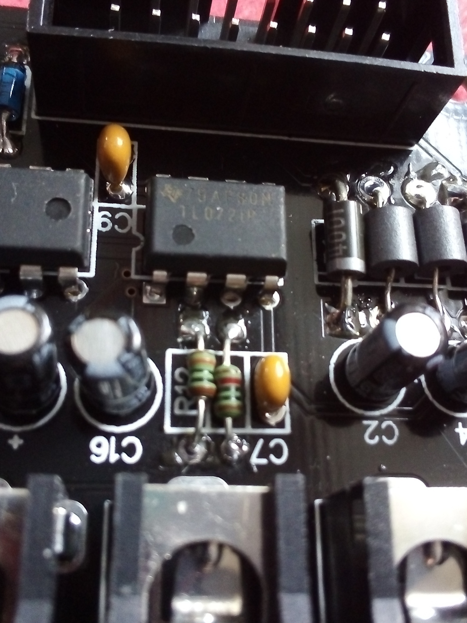
btw, one of the C2 cap legs is an example of a pad that would be connected to V+ or V-
Sounds like a short!
Can you use your multimeter in continuity mode and connect both probes to +12v and GND, then GND and -12v and also +12v and -12v. If you hear a tone, there may be a short between the two pins.
Transistorcat suggested measuring resistance across the same points, so I suggest doing both methods and reporting back. If there is in fact a copper level error, you may need to buy yourself a nice magnifying glass to find it.
Thanks @transistorcat & @Fox
I’ll get trying at now.
I had the same problem with Counter. It ended up being U2. Those pads are so close together. Had to fix the soldering three times before it reliably worked.
My multimeter doesn’t beep but show a one when there’s no connection and generally drops to zero when there is. Between the +12V pin that’s further away from the pcb edge & the diagonal ground pin in the next row, it goes to 747 or 748 on multiple tests. I desoldered and then resoldered the 3 leg transistor just in case. I plugged it into the case, the +12V led on the power board went out, the - 12V remains on. The chips don’t heat up, no bad (Burning) smells or magic smoke thankfully.
Really, the same problem, it shut down your system when plugged in? That’s great to read that you fixed it
Yes, exact same thing. Whole system would not power up with Counter plugged in until getting the soldering on that little guy exactly right. But, yes, did eventually work.
(Admittedly, my first attempt at soldering that thing was a total mess.)
Maybe like yourself @sean, I’ll get lucky 3rd time. I’ve got no flux here which would surely help
I’ve desoldered & removed the U2 transistor, it’s a 7805 so ya, converting the incoming +12V to 5V. I measured the pads & the middle pad & furthest from the PCB edge don’t go to one but 650 or there abouts on the multimeter. Hum, I’ll bring it with me when I visit a friend early next week, hopefully he find the exact issue after a quick look.
Now I realise that with such close pin legs, the obvious technique is to solder the outer legs on one side of the pcb & the middle leg on the opposite side to limit the chance of a short.
By any chance do you still have the castle module that gave you that trouble @transistorcat? If so, could you please take a photo when it suits you of where you made that cut, I’m really curious.
Thanks for taking the time to disconnect the module from your setup & to take the photo @transistorcat
I see what you mean about the flux clean up but you got it working & the PCBs usually stay hidden away in their warm, dark borrow were eyes fear to thread.
And your system had the same symptoms when you plugged it in? No power that is.
I think this specific short manifested as a broken (always low) output
Ughh, sorry for not updating this thread but taking the module over to my mate, applying some flux and reflowing the solder on the U2 transistor pads did the trick
Thanks again to everyone who chimed in & helped out 
Glad to hear you worked it out. I had to enlist the help of a friend too.
Would certainly be in favor of future boards having the pads spread out a little. Would rather bend some legs than struggle over my shaky soldering hands quite as much.