So, after some discussion with @rempesm and others about the alternative builds of the Scaler, we decided it needs a topic to discuss the options.
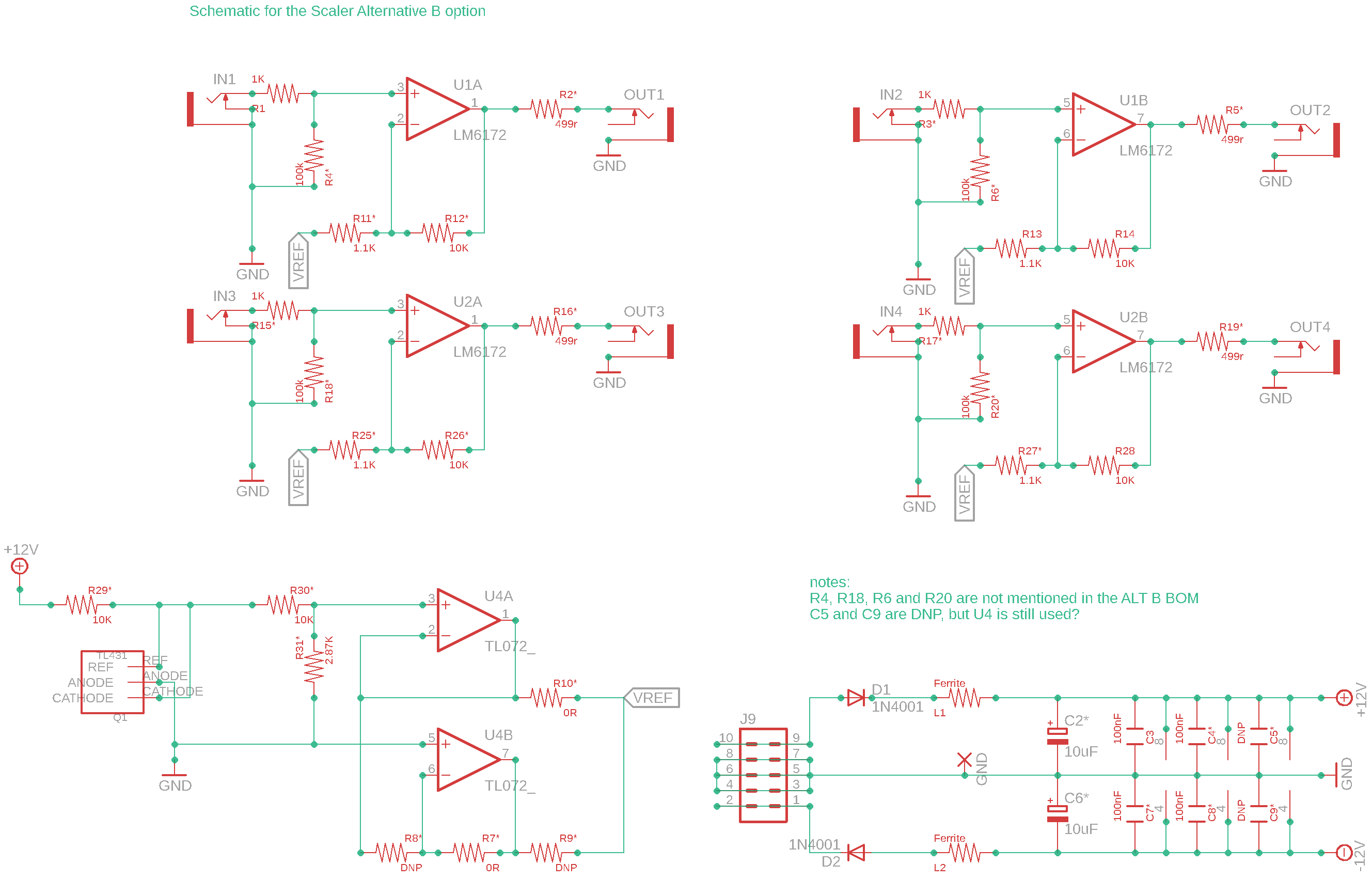
I have layed out the ALT B schematic with the values as described in the Alt B BOM.
(newest version from Github) This might shed some light on the question if this version scales from 0-1v to -5+5v
As far as I can tell, the voltage reference is used (R30 and R31 have specific values) to pull down the voltage to get bipolarity. U4 is placed (but for some reason C5 and C9 are not)
Notes:
R4, R18, R6 and R20 are not mentioned in the ALT B BOM .
I set these values to 100k, as used in the ALT A BOM and schematic.
C5 and C9 are DNP, but U4 is still used?
R1/R4 are a voltage divider, so they can be used to scale down voltage ranges.
On a typical LZX cadet they’re often there, as 499R/100K, so inputs lose 0.5% of their voltage swing. In theory you might think you’d be better off without populating R4, to get 100% of your input voltage at the op-amp + input and not lose a tiny bit to ground, but then the op-amp input would be Not Connected when nothing is plugged in to the socket, which could cause unpredictable voltage fluctuations on the op-amp output. So it’s usually populated, as a trade-off to ensure empty sockets give 0V output on the buffer op-amp in this case.
I’d populate it with 100K (or greater) just as you’ve done.
C5 and C9 obviously should be populated for good practice, if you’re populating U4. But it’s only a TL072 so not all that bad.
Basically I agree with everything you’ve said and done
Interestingly, as a consequence of this in a down-scaling scaler alternative that populates the R1/R4 (etc) voltage divider with significantly different voltages the impedance of the module will be different too. But I think that is only really important if you’re patching in to it with passive multiples.
I’m going to build this one (just waiting on a few parts) and will confirm if it works. I have the other permutations (1V->5V, 5V->1V, +/-5V->1V) built so far.
@reverselandfill I built your schematic above this evening and it checks out fine on the scope. Thanks for puzzling that out!
@Z0NK0UT, would it be possible to update LZX’s BOM here to be relabeled as 0-1V to +/-5V instead of the other way around. The only errors are that R4, R18, R6, and R20 should be 100k resistors and C5 and C9 should be 100nf caps.
The +/-5V to 0-1V BOM here is correct on the scope as well and could be added to the site to cover most conversions folks would be after.
I’m about to build 2 of these (one to get in and one to get out of audio eurorack) and I’m wondering what the advantage of converting to 0-1v over +/-1v is. For instance if I send a bibolar lfo swinging +/- 5V to 0-1v scaler does that mean the LFO will now swing above and below .5v or will the negative portion be cut? Similarly, if I send a unipolar 0-5v envelope into a +/- 5V to 0-1v scaler I assume the output is not a constant .5v rising to 1v upon trigger right? Am I missing something simple?
And vice versa, if I am sending a cadet vco out to audio land to a filter or divider or whatever “expecting” a bipolar voltage is there an advantage to only sending 0-1v out as opposed to +/-1v to +/-5v?
I know there are workarounds using offsets, just curious how these work exactly.
For instance if I send a bibolar lfo swinging +/- 5V to 0-1v scaler does that mean the LFO will now swing above and below .5v or will the negative portion be cut?
if you send a +/-5V LFO to the +/-5V to 0-1V scaler, the entire LFO will fall within the range of 0-1V. essentially it divides the signal by five and adds a 0.5V offset to bring the whole thing within the positive range. if you send that same +/-5V LFO to the +/-5V to +/-1V scaler, the negative portion of the signal will show up as black, effectively adding black spaces between the positive segments of your LFO.
if I am sending a cadet vco out to audio land to a filter or divider or whatever “expecting” a bipolar voltage is there an advantage to only sending 0-1v out as opposed to +/-1v to +/-5v?
this really depends on your use case. if you’re trying to use video oscillators in the audio realm (or as bipolar modulation sources) then definitely stick with the 0-1V to +/-5V. send those same 0-1V signals to the +/-1V to +/-5V Cadet and you’ll have oscillators with a DC offset - since video oscillators only range from 0-1V, you’ll never get any negative portions of the signal. i guess if you want to use them as envelopes or absolutely need unipolar modulation then this would be the way to go - otherwise i’d stick with the 0-1V to +/-5V configuration.
i built myself one of each Cadet V Scaler but in practice i mostly find myself using the +/-5V to 0-1V and 0-1V to +/-5V pair.
Thanks, this is exactly what I was looking for! I’ll stick with +/-5V to 0-1V and 0-1v to +/- 5v (it’s much easier for me to apply offsets once I’m back out of lzx if I need to for slower unipolar modulation, or to attenuate a bipolar signal down to less than +/- 1v without offsetting to send into lzx). I suppose what I’m lacking or need will become more apparent once I get something up and running.
@rempesm - The +/-5V to 0-1V BOM you linked sits in a Google folder and I’ve just posted an access request there for it. If you’re not in control of that access and have a copy somewhere of the BOM file you originally linked, are you able to share that? I’m not confident that the +/-5V to 0-1V BOM on the LZX Github has been updated.
Hey all, I am a complete idiot and have virtually no idea how electronics work under the hood. I have built DIY projects, but solely via following instructions and painting by numbers.
My question is this: is it possible to mod or build a Cadet scaler to convert to 10 volt standards rather than 5 volt?
Specifically I am salivating for the Tiptip Audio Buchla clone of the 266 Source of Uncertainty. All Buchla CVs are zero to ten volts.
I got some preassembled Cadet scalers from a Reverb store, Poisoned Modules. But these are all 5v to 1v, +/- 5v to 1v, and 1v to 5v.
To handle Buchla CVs, what I really need is 10v to 1v, and 1v to 10v. Is that a possibility with the Cadet V? If so, how do I make it happen? Is it something a novice like me can do by swapping out some resistor or something?
Yeah! In fact, it will be super easy. Let’s look at the 5V to 1V configuration first. Modifying this one to perform 10V to 1V will be as easy as changing one resistor value. Here is the schematic to see which resistors we’re changing:
This one simply uses a resistor divider to attenuate the input by a ratio of 5:1. The resistor pairs R1&R4, R3&R6, R15&R18 and R17&R20 are the driving forces for the attenuation. Instead of a resistor divider of 20K and 4.99K, the simplest method would be to add another 4.99K in parallel with the existing 4.99K.
So my suggestion is to solder a 4.99K resistor in parallel with R4, R6, R18 and R20.
This one will be easy too if you want to modify the original 1V to 5V config, found here:
In this config, the main driving force is the op amp gain created by the resistor pairs R11&R12, R13&R14, R25&R26, R27&R28. By swapping the 2.49K resistors (R11, R13, R25 and R27) with a 1.1K resistor give you the gain you need. 1.1K is certainly a strange value, but you could make it up with a 1K and 100R in series.
I would have suggested putting another 2.49K resistor in parallel with the existing 2.49K resistors, but the gain was a little off. I don’t have much experience with audio modules, but I think the general consensus is a 1K series resistance on the outputs. This will add to the 1K series resistance on the input of the Scaler module and effect the attenuation that naturally occurs with the 100K termination resistor. Keeping that in mind, we want our gain to be ever so slightly above 10x.
I also have a Make Noise Maths. Looking at its manual, many of the outputs are +/- 10 volts. What would be the Cadet V configurations for converting bipolar 10 volt signals to and from LZX unipolar 1 volt standard?
Thanks…! Of course one of the official builds is +/- 5v to 1v, so +/- 10v to 1v seems logical enough.
Drilling into the Maths manual, it doesn’t differentiate between audio and CVs. It accepts negative CVs, so in a perfect world it would be awesome to convert 0-1v LZX ecosystem CVs to +/- 10v.
Note that Maths isn’t going to be able to process video signals very well. It almost certainly is not design for the high frequencies of video signals. So if that’s your intent, it probably won’t work well. For instance, horizontal bars might work OK(-ish?) but vertical bars most likely won’t work well. And it’ll work even worse if you’re processing a 0-10V or +/-10V signal than it will if you’re processing a 0-1V signal.
Also, in case you haven’t thought of this: if all you want is to trigger the Maths, you shouldn’t need to scale a 0-1V signal up that much (or at all?). I’m not sure what the input trigger voltage is on a Maths, but it’s almost certainly less than 5V, otherwise other eurorack gear would have trouble triggering it. I have a Function, and it triggers with 5V (or less, I haven’t researched or tested to see how low triggers it).