Another update: using weaker pull-up/pull- down resistors (a higher value) doesn’t fix the issue in non-genlocked mode, and stronger pull-up/pull-down resistors result in a significant horizontal shift of the external signal when in genlocked mode. Tried to find a suitable in-between value, but wasn’t satisfied with the result.
Ran into a similar issue with my own sync gen, since the genlock part is based out of the Cadet. While checking CD4046 datasheet in closer details, it appears that the Phase Pulse output (pin 1) is held low in non-genlocked mode, as the PLL doesn’t have any external Hsync to compare the Hsync generated by the Atmega/VCXO to, and it is held high when the internal Hsync successfully genlocked to the external Hsync.
So a normally closed switch can be used to switch on the 10k pull-up/pull-down resistors when in non-genlocked mode, and then switch them off when in genlocked mode based on the state of the Phase Pulse output.
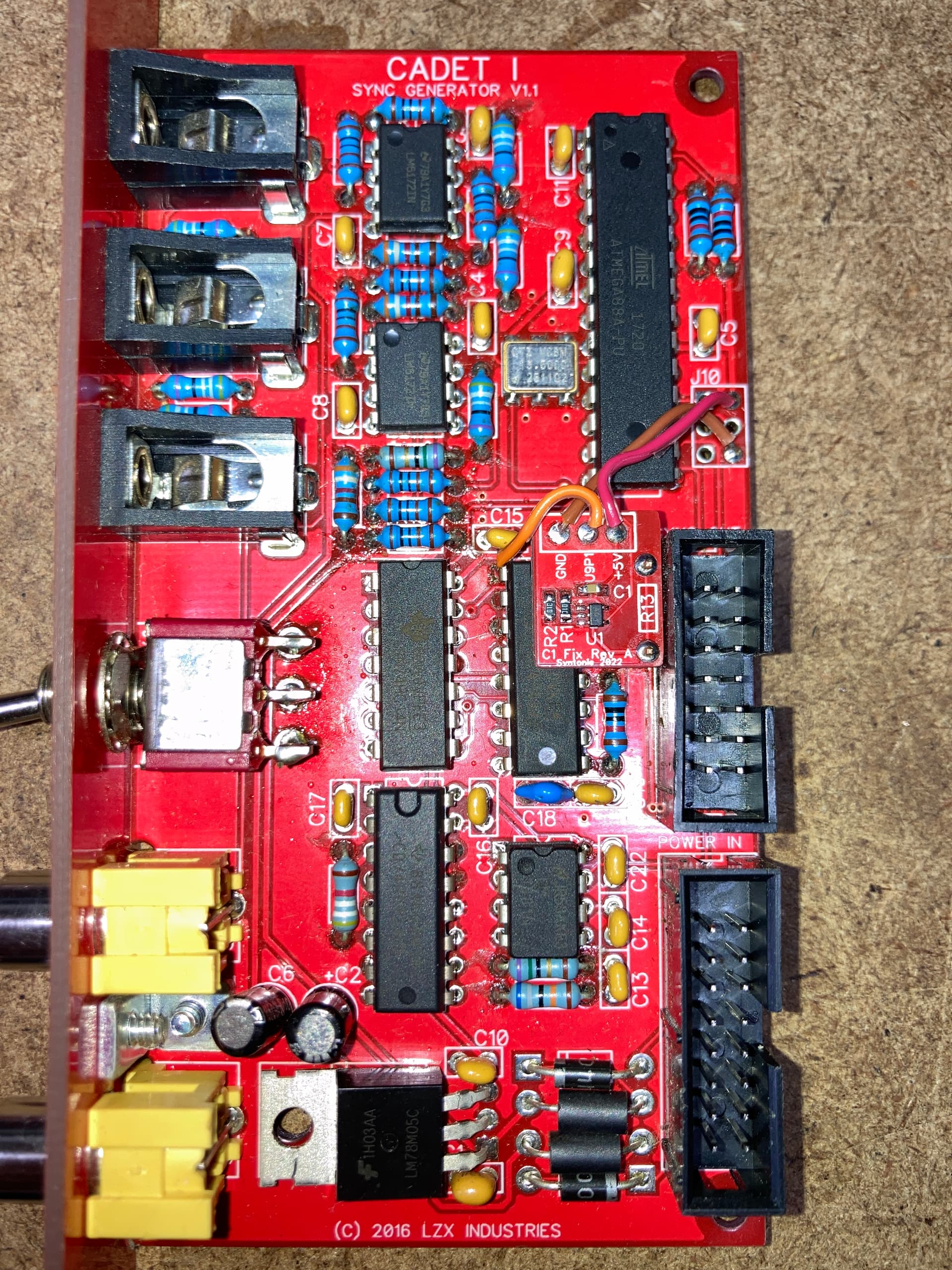
Made a tiny add-on board that can be soldered in place of R13, it requires to be wired to 5V/GND (I used the pads from the ISP connector) and also U9 pin 1.
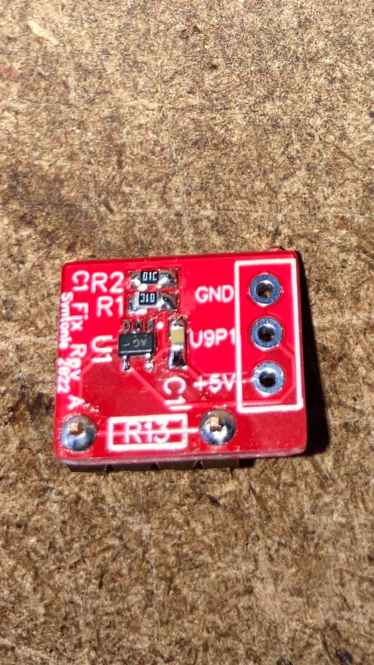
Not sure if it is of any interest as it is mostly an issue with BM Analog to SDI and it’s easily fixed by plugging the sync gen to an external source, then got a few extra boards that I’ll happily give away as I only have one Cadet I. The CMOS switch is a little tiny but fairly easy to solder with a thin tip iron, passive components are 0806 and a 4pin 2.54mm header with the 2 middle pins removed is used to solder it to the Cadet board. Also happy to put the gerbers/BOM on GitHub if it is useful to anyone (else than me lol).