Hi All, I have a Blackmagic Design Analog to SDI Mini Converter that doesn’t seem to like the composite video from my Cadet RGB Encoder. The symptom is a very jittery picture that jumps sideways.
I’ve tested the 525i SDI signal into both a BMD Web Presenter and an ATEM Studio HD (current model) with the same results. I tested with a cheap Canon camcorder and got even worse results (dropouts), but I get a clean conversion with my Andor 1.
Sounds like an issue with the Analog to SDI if you are having trouble with two sources. The issue sounds like a sync tolerance problem. Have you tried updating the Analog to SDI to the most recent firmware?
I talked to BMD tech support this morning and ran through all the tests while I was on the phone. The camcorder’s composite output magically started working fine (it was previously the worst of the three), which means 2 out of 3 voted against the C2. The proof came when I plugged the camcorder’s composite output into the C1’s input and everything cleared up. This works with the Andor 1 also.
Thats not too surprising. Both C1, Vidiot, and the original Video Sync Generator use the same sync gen architecture, which is based on a 13.5MHz voltage controlled master clock (same as BT656 SD pixel clock timings.) It appears that the resting frequency of the clock is outside the expected range of the Analog to SDI, which explains why it works when genlocked to the timing of the external device. So you have some options: sync all your gear to a master reference signal, run the C2 through a frame sync/TBC, or try to modify C1 to get its native frequency in range. I would be happy to help with the latter, you could start by trying to add 10K pull-up and pull down resistors to the VCXO CV input.
Hope you don’t mind the old thread digging, was looking for information on PLL/VCXO, and just found about this thread.
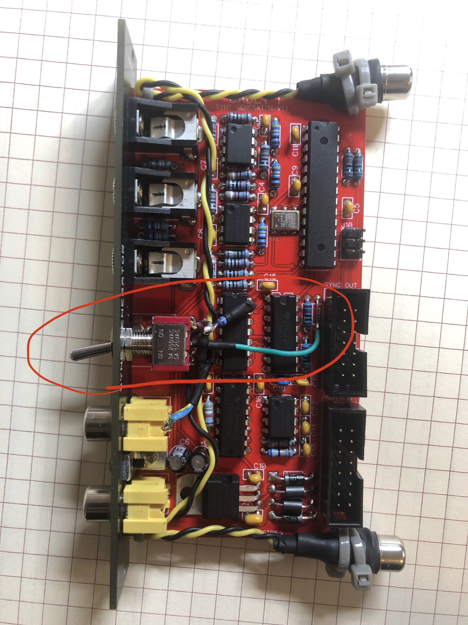
I had really minor issues with Cadet I and BM Analog to SDI, mainly a little colored line as shown on the picture, and rarely some drop, which didn’t happen when Cadet I was synced to an external source as mentioned here.
Thank you for bumping this! My BMD Analog to SDI acts really erratic when it’s receiving sync just from my Cadet I. I usually sync my whole system to Memory Palace → Cadet I which prevents this error and helps other picky parts of the system cooperate but I’m gonna try this now to see if it works direct!
An update on the mod, I had issue syncing to an external source coming from a cheap HDMI to composite converter, image was stable but started in the middle of the screen. Since I was in a different setup (Cadet RGB encoder going to Edirol V8 before BM Analog to SDI), I removed the resistors and everything was fine. I suppose it mostly comes from the HDMI to composite converter which are known for outputting slightly out of specs signals, will put the mod back and do more tests.
I forgot to update that I tried this and while it worked perfectly for Cadet I running natively into the BMD Analog → SDI, as soon as I plugged in a Memory Palace to genlock it, the image was stable but shifted significantly over to the right. Clipping the resistors made Memory Palace as the genlocked source work fine but Cadet I is back to making the BMD Analog → SDI unhappy. I haven’t tried genlocking the Cadet I to other sources with the mod in place yet.
I’ll have to try some different values–any suggestions @syntonie?
I would try with weaker pull-up/down resistors (100k), as this may mitigate their effect when in genlocked mode, while keeping VCXO CV to Vcc/2 otherwise. Will give it a go and report.
Another update: using weaker pull-up/pull- down resistors (a higher value) doesn’t fix the issue in non-genlocked mode, and stronger pull-up/pull-down resistors result in a significant horizontal shift of the external signal when in genlocked mode. Tried to find a suitable in-between value, but wasn’t satisfied with the result.
Ran into a similar issue with my own sync gen, since the genlock part is based out of the Cadet. While checking CD4046 datasheet in closer details, it appears that the Phase Pulse output (pin 1) is held low in non-genlocked mode, as the PLL doesn’t have any external Hsync to compare the Hsync generated by the Atmega/VCXO to, and it is held high when the internal Hsync successfully genlocked to the external Hsync.
So a normally closed switch can be used to switch on the 10k pull-up/pull-down resistors when in non-genlocked mode, and then switch them off when in genlocked mode based on the state of the Phase Pulse output.
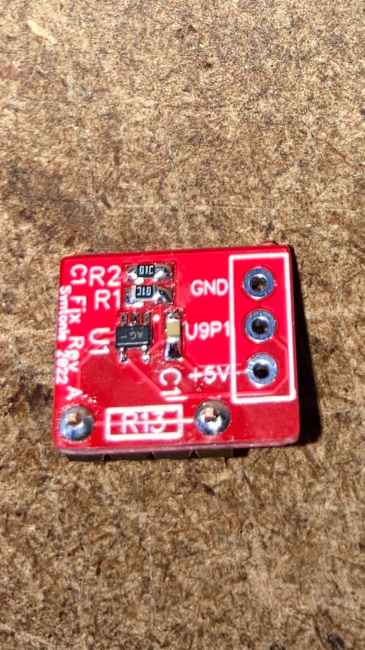
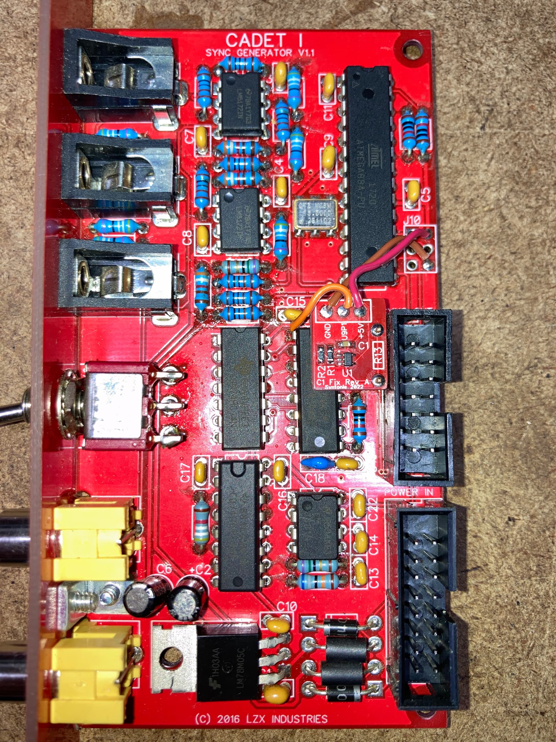
Made a tiny add-on board that can be soldered in place of R13, it requires to be wired to 5V/GND (I used the pads from the ISP connector) and also U9 pin 1.
Not sure if it is of any interest as it is mostly an issue with BM Analog to SDI and it’s easily fixed by plugging the sync gen to an external source, then got a few extra boards that I’ll happily give away as I only have one Cadet I. The CMOS switch is a little tiny but fairly easy to solder with a thin tip iron, passive components are 0806 and a 4pin 2.54mm header with the 2 middle pins removed is used to solder it to the Cadet board. Also happy to put the gerbers/BOM on GitHub if it is useful to anyone (else than me lol).
Ah we were kind of on the same track, switching those resistors out when not used! And I guess you hardwired the NTSC/PAL switch to the desired format, as there is not many reasons to switch from one to another often.
Looks like the CMOS switch I’m using (NS5B1G384DF) is currently out of stock from Mouser, got them from RS in the UK, so can also include this with the board if you want. I initially used a normally open switch on my sync gen board, thinking I would do the external signal detection with the FPGA and use it to switch it on and off, but since the genlock is done externally, only Odd/Even from the external signal is coming to the FPGA, so realized it would be much simpler to use the PLL Phase Pulse out and change the switch to a normally closed one.