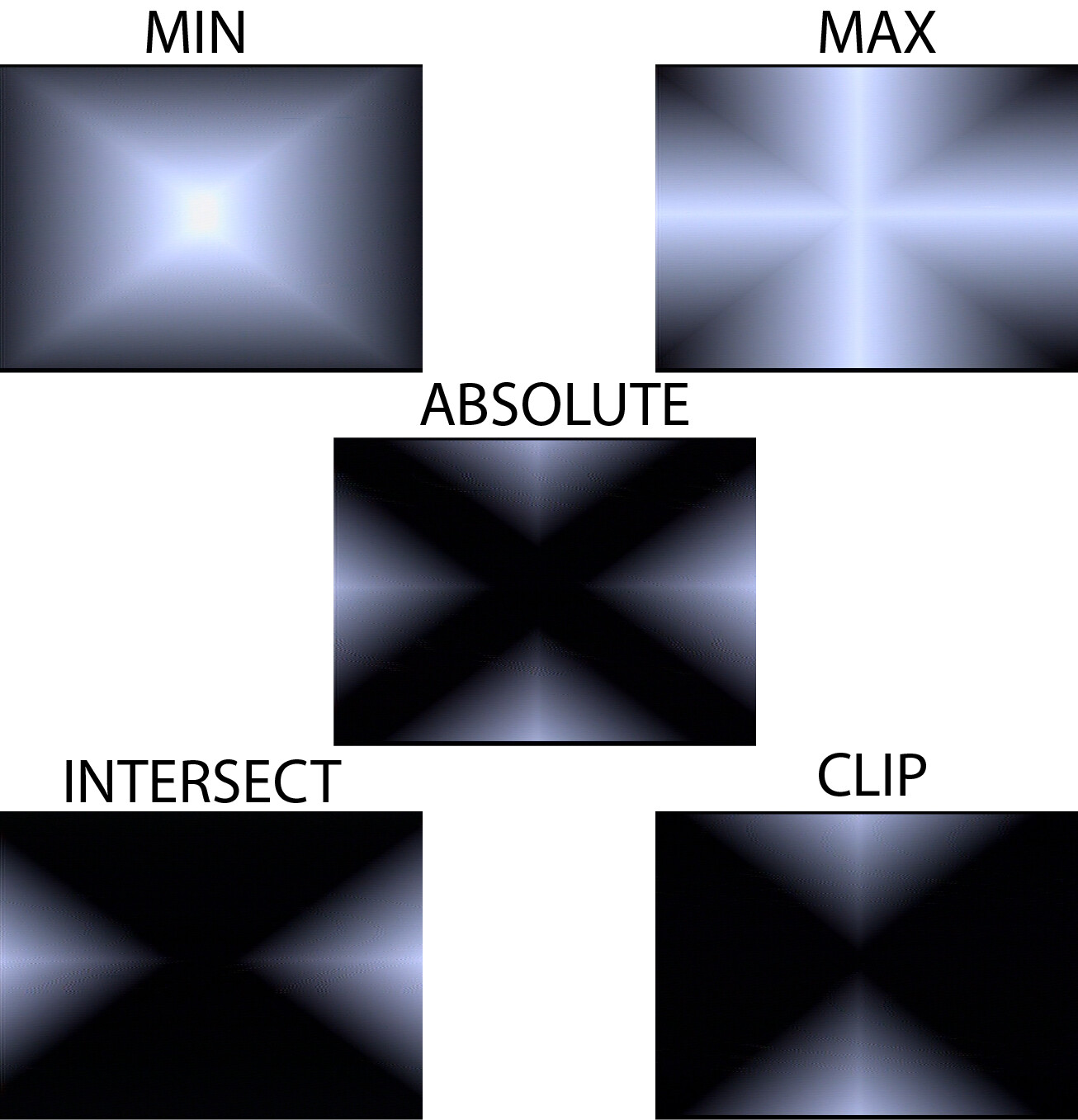
Greetings logicians, would anybody be interested in this for a DIY project? I believe its the same circuit as arch, but I’ve never owned one, so I’m only guessing. Photo below shows the outputs when using an H/V Triangle ramp on inputs A and B. Please excuse the noise its still on a breadboard…
In the photo above,
intersect = MAX minus INPUT A
clip = MAX minus INPUT B
is this correct? or should I subtract from ABS instead of MAX?
Anyone have any ideas on how to make it differ from arch? Third input? More logic trickery? It has 6 (or 7) lm6172’s, so its looking like a rather expensive build as it is. Processors, function generators, and faders are real fun with this, but including it within the circuit could make it expensive for those who already have those to spare.
Nice. I was thinking of trying to make something similar a while ago but I put it on the back burner before I really made any progress on it. Now I don’t need to!
I think it’d be handy to have inverted outputs for each output (inverted around 0.5V, that is). I love having more outputs.
Regarding opamps and cost, you could keep costs down by using the ones LZX are using now (ADA4851-4), but they’re not through-hole, so they’re not as DIY friendly, so it’s a trade off. But I believe you can get a quad package for about what a dual package LM6172 goes for.
having at least one built in offset would be pretty handy.
if nothing is patched into one of the inputs it could work as an offset and then if something is patched in it could be an attenuator.
Honestly though if it still worked as an offset with something else plugged in and just clipped at full white it would be great. I always have a passage feeding my arch and it was helpful to really dial things in.
I was also thinking of some inverting/ offset. Would it be better pre or post logic? Adding +/- offset post logic (especially to ABS, intersect, and clip) lets you dial in the overall output (size/intensity) for nice overlays. But attenuvert and offset pre logic allows you to shape an input to effect the way the logic circuit itself is working. (i’ll probably do this with at least one input, clipped to 0-1v?)
What’re yall’z thoughts? We’re getting pretty high on op amps, does anybody care?
I’ve been considering going the ADA4851 route for some time now. I’m just a bitch when it comes to believing in myself to solder smd (the exact way I felt when I first got into DIY and didnt believe that i could ever solder )
What’s others opinions on going smd? If I had enough op amps, I’m so willing to get a lil weird with this.
Flux, braid and a magnifying glass makes this all possible with just an iron. A hot air gun is worthwhile checking out so surface tension just takes care of it for you but I’ve soldered tons of TSSOP packages with an iron.
Neat ideas on having attenuvert+bias pre/post on the logic inputs. Logical voltage processor?
Smd all the way.
I thought the same, I wouldn’t ever be able to ;and now is a realaxing exercise Fridays after work
Also with a high opamp amount, 4851 will quite reduce the costs.
Check the Mystic Circuits’ Ana.
It has basically what we are describing here.
Two inputs mixed, one with attenuverter normaled to Vin if nothing connected.
I’ve been playing with the idea of a “Triana”, meaning 3 of what we are talking about (only max,min and Abs though) and some extras in one panel. @jreinke I can send you what I have so far if you’d like to collaborate on it.
So down! I’m always thinking RGB. 3 channels would be so tight.
I have looked into Ana (also tree, Mystic Circuits is dooope). Although this was a pretty recent A-ha moment, and the idea didn’t make sense to me a week ago lol. I’d love to see what you’ve drawn up!
Personally don’t think I’m comfortable making the leap to SMD — can just barely manage thru-hole components with my lousy soldering skills — but the SMD op-amps really do make more sense.
If you’re adding functionality, I think pre-logic offset makes more sense to me than post-logic mixing, since the latter might beg for something more complex than you’d reasonably build into this (like a full matrix mixer).
I know I suggested adding a sum output, but I was literally just thinking a simple sum of the two inputs (rather than of the logic outputs), clipped at 1v. That would expand the range of output brightnesses (clip/intersect < absolute < min < max < sum).
Also, just throwing this out there, if you — or anyone else — ever want any help visualizing panel layouts, I am happy to help out with that (to be clear: panels, not PCBs).
I don’t know much/anything about electronics, but graphic design is my day job, so mockups like the ones I’ve done on my silly module idea thread are fairly trivial for me to produce.
So, yeah, if anything like that would be helpful, happy to lend a hand on that.