Soooooooooooooooo I’ve ordered a MemoryPalace and was thinking on how my workflow could be with it! And to be honest I would love to use the MP as final stage + encoder because of the HDMI outputs…
The problem if I do it this way, I won’t be able to use my Visual Cortex’s mixing+keying section (which I love and use a lot) , because cortex don’t have RGB LZX lvl outputs, so I can only use it as encoder final mixer… unless
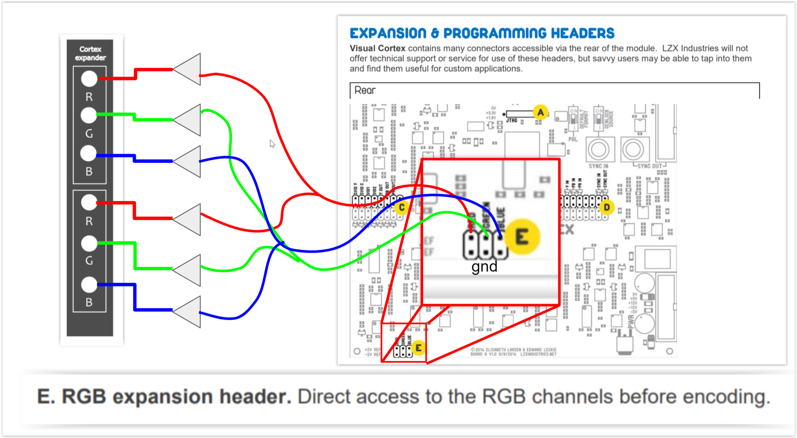
I want to use the hidden treasures of the Cortex, pre-encoder expanders. So my plan is to build a small PCB of maybe 2hp or 4hp, that has the pre-encoder outputs of the mixer as a double buffered outputs (will be using those 6172 @pbalj that we purchased)
I wanted to share the idea to double check how feasible is, but also to know if any of you find it interesting, or if I’m missing something or a mistake).
With this expander, I can use VC super duper mixing capabilities and send it to the MP inputs!
@luix did you end up building this? Has anyone else considered it? I might give it a shot this weekend (one set of outputs, without buffers, to start.)
For some reason, I thought the MP had a composite input, but I was sorely mistaken.
I’m not really a DIY guy, but I’d be willing to chip some $ in for the cause. This looks fairly simple though, so if it was a simple PCB, my shakey hands could probably solder it.
I have a composite to component adapter that has an RGB option, but I doubt it will work without some sort of attenuation to the 1v spec.
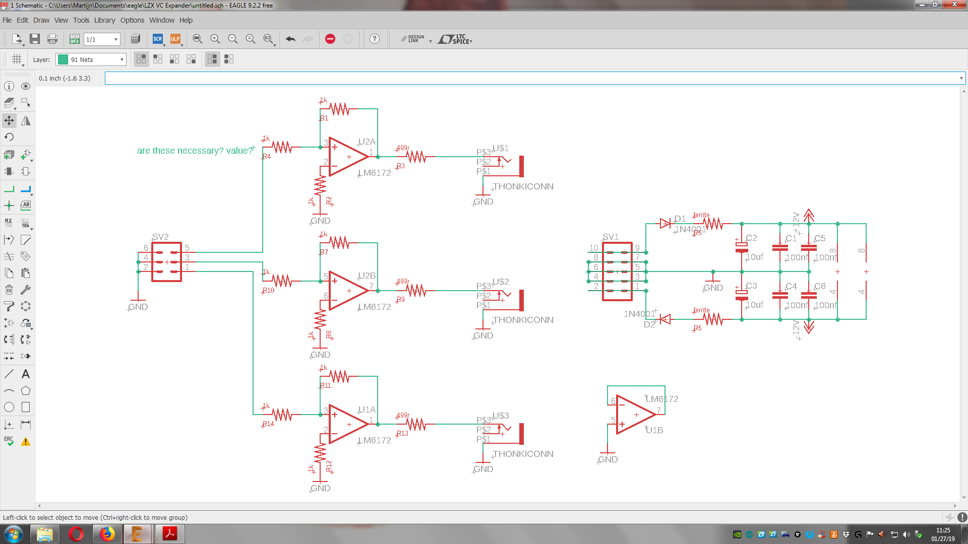
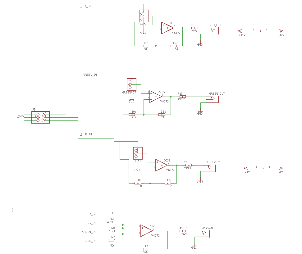
something like this? please correct any mistakes!
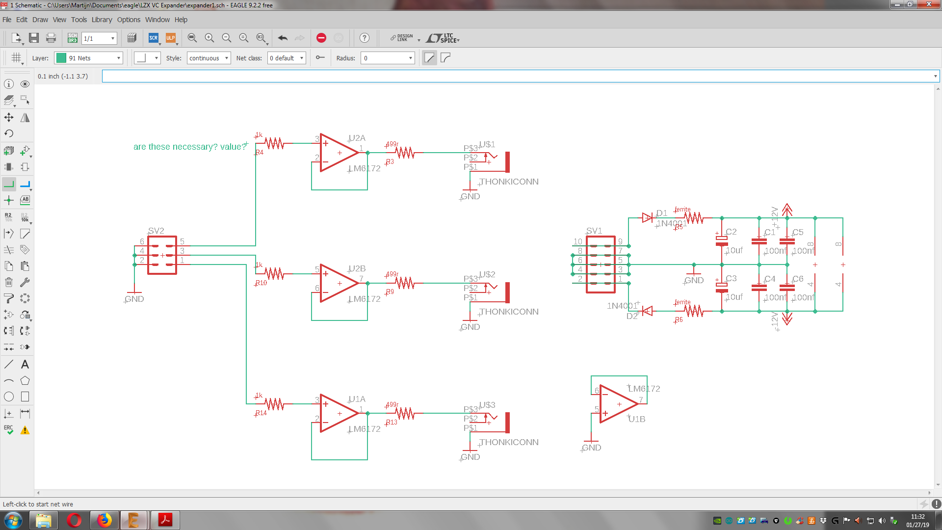
I’ve made 3 outputs now. Easy to double up if that is needed.
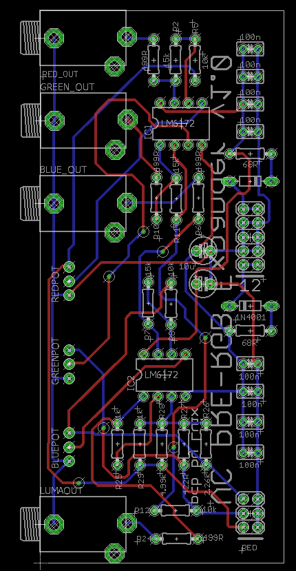
Maybe the buffers should be without resistors.? - pic2
Sorry for the super late response… I’ve been sick and bed the last week and couldn’t post anything.
The answering all of you, YES, I have a pcb design for this. Back in november I worked a bit on the breadboard and the crossed some conclussions with Lars on how to do this in the most interesting way.
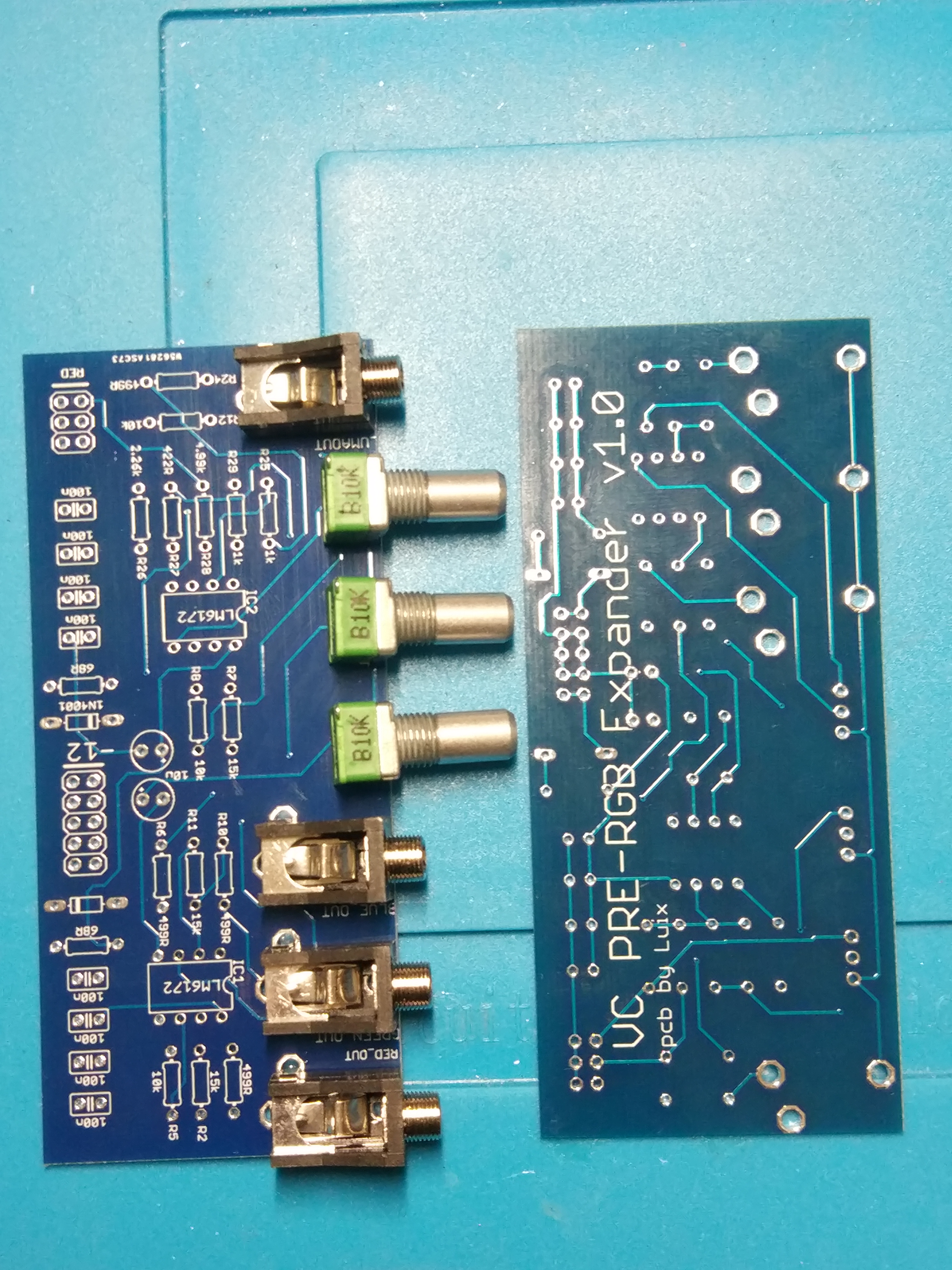
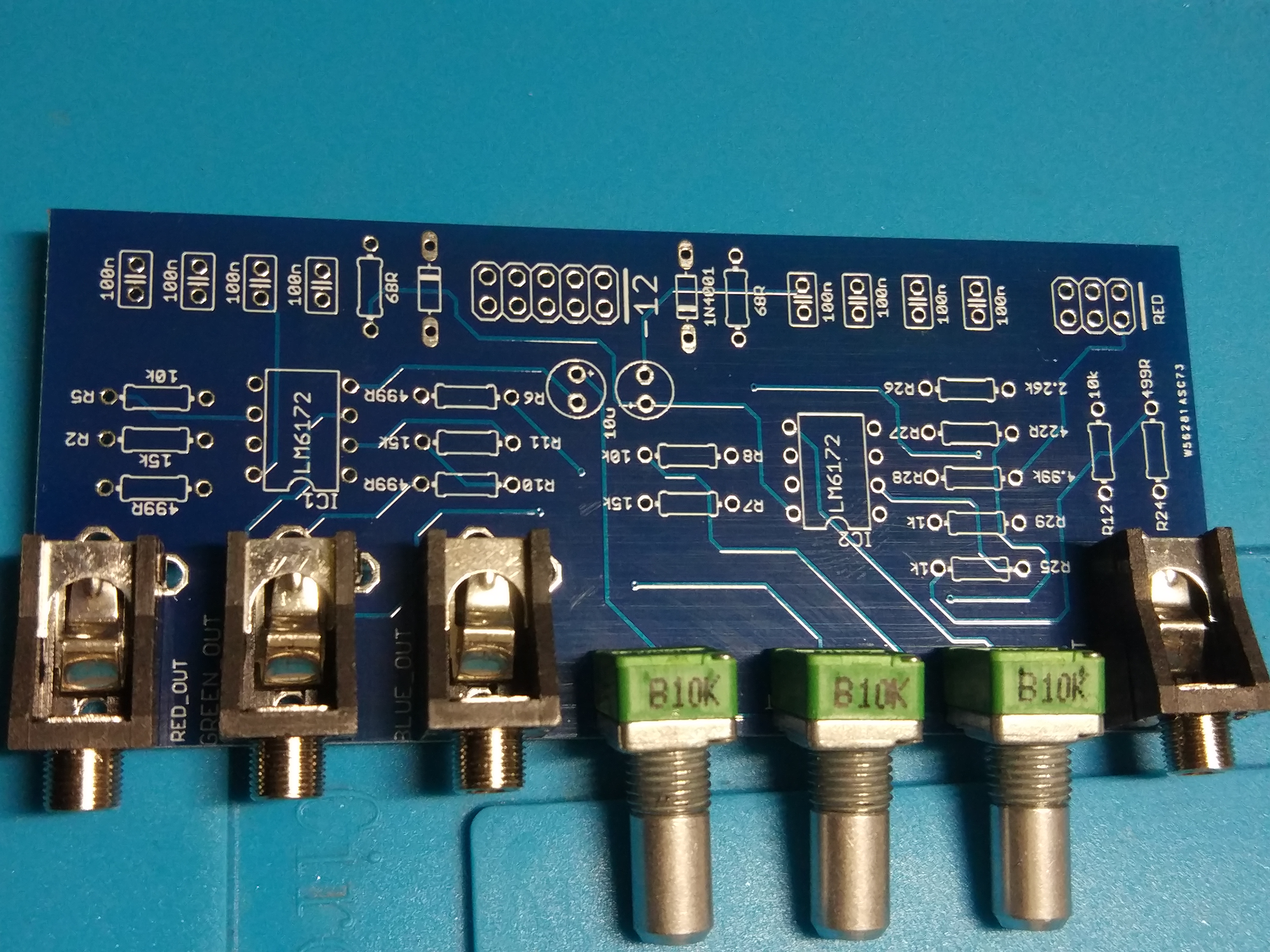
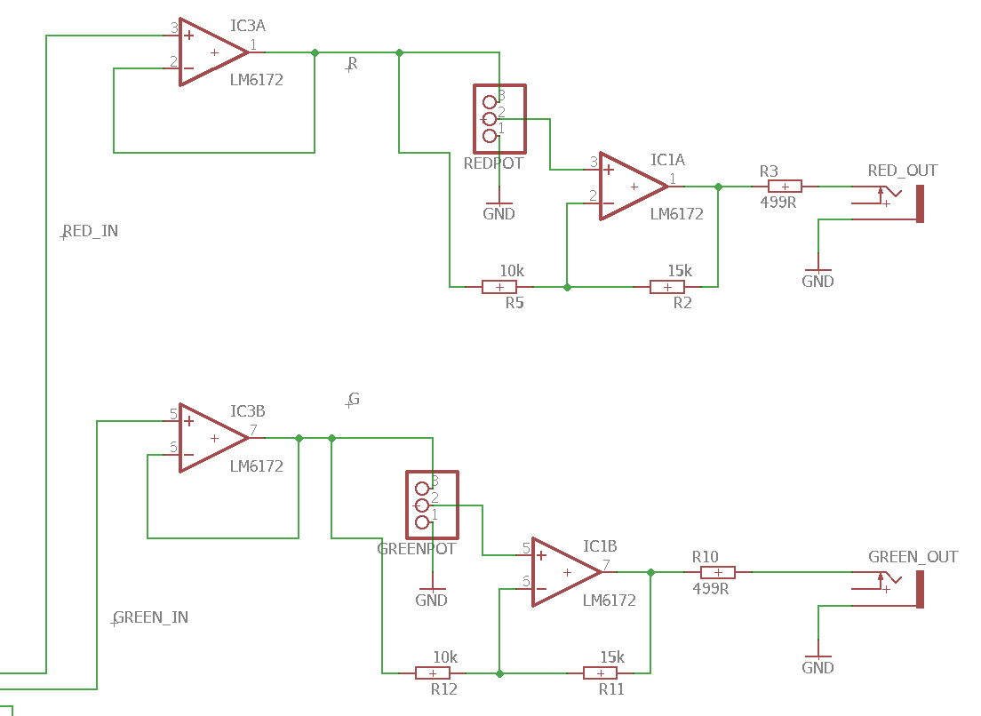
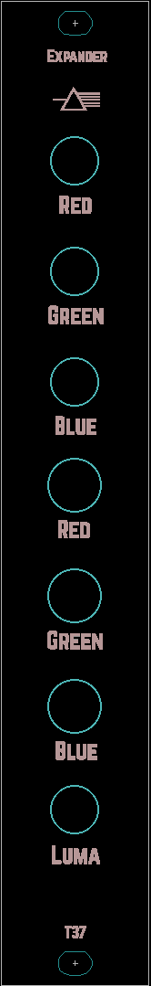
The first approach was as @reverselandfill said just to use buffers, but Lars suggested to add attenuverters in the outputs to be able to invert the output signal of the cortex, also a LUMA OUT is super handy specially to patch in the alpha channel of the Memory Palace, here are some pics.
On the second schematic you made, the R4, R10 and R14 are not needed. I made almost the same design and Lars said those resistors are not needed but the signals come from a known world (impedance, levels, etc…) the pins could go directly in the non-inverting inputs of the op-amps.
RGB to Luma is very handy (and a cheap addition!) Someone should do YUV to RGB and RGB to YUV boards at some point. If you had UV, you could patch up a chroma keyer with some Castle logic and some C8s!
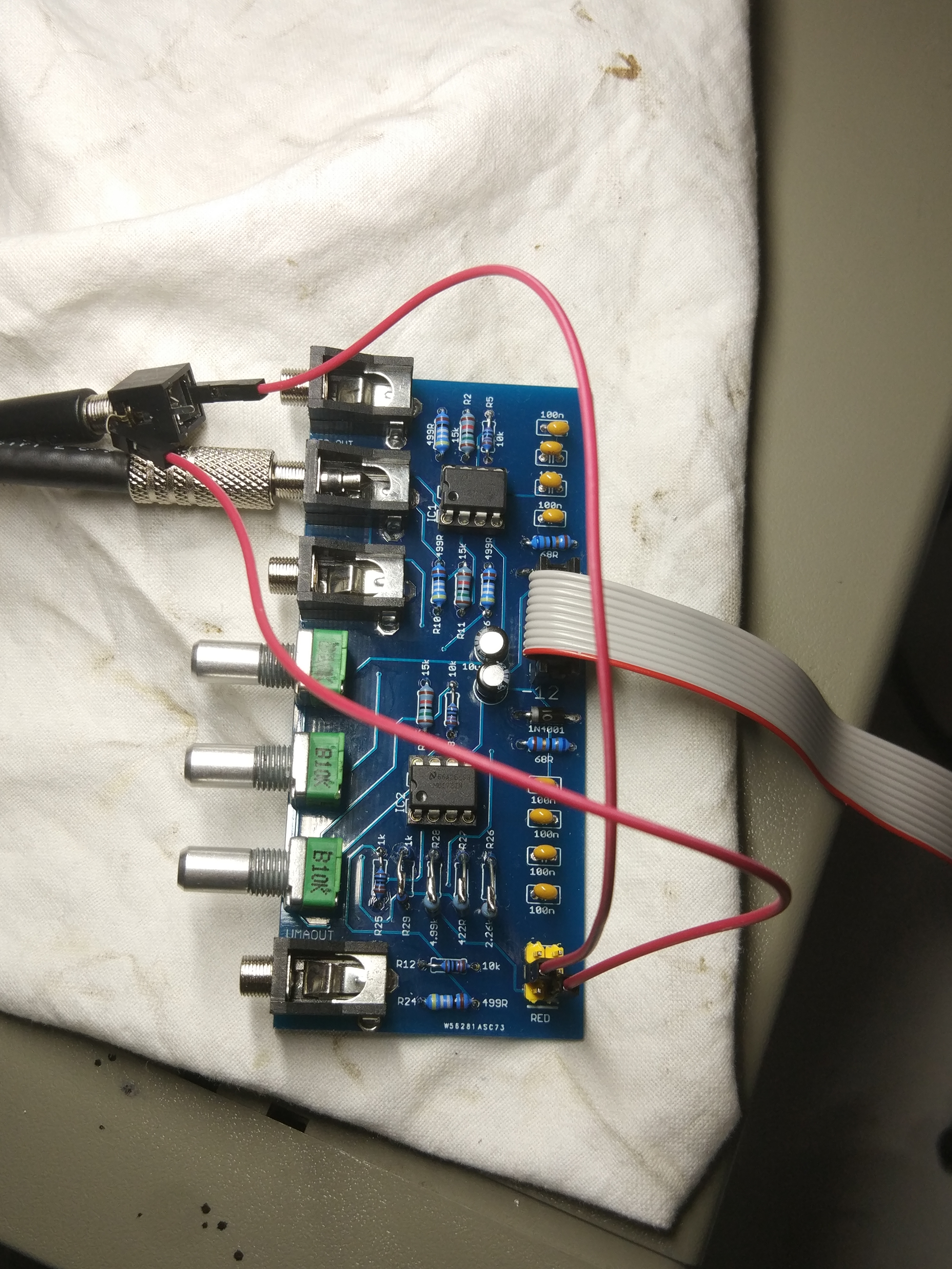
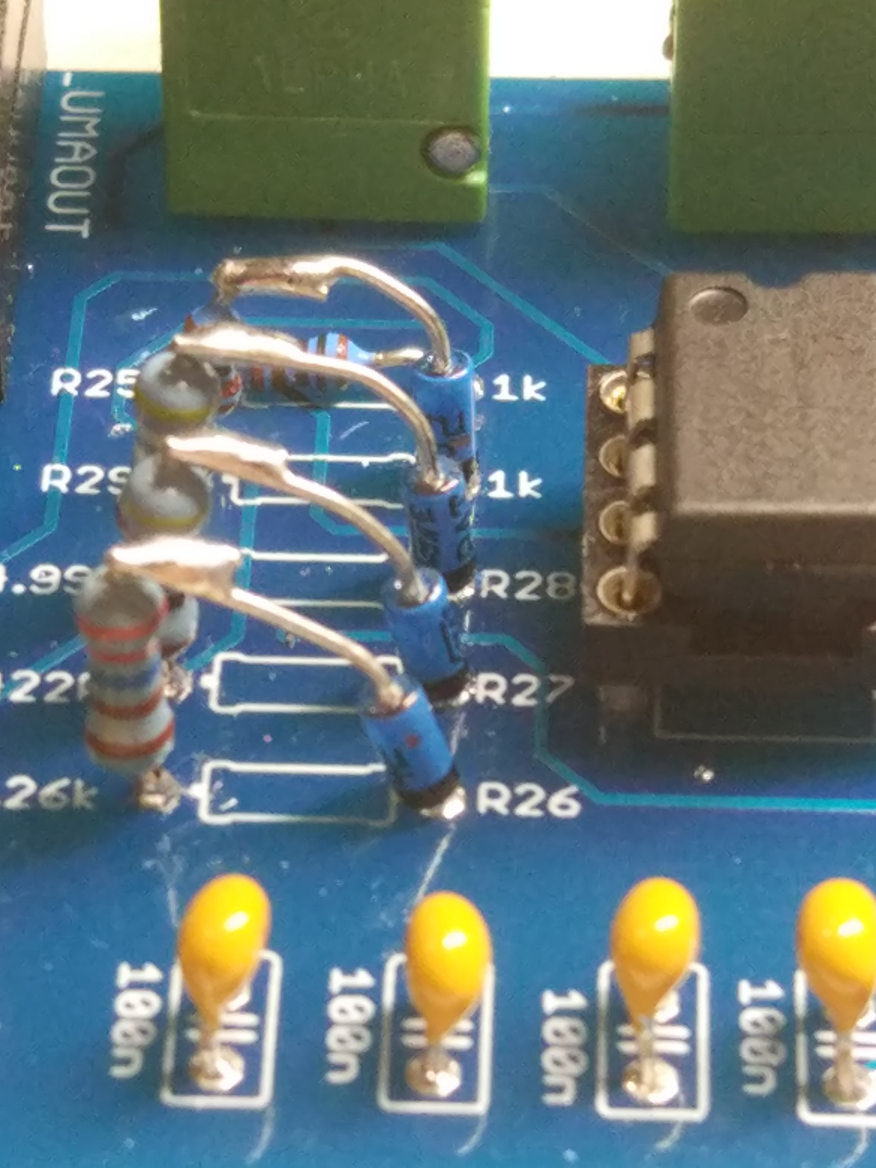
So I finally pulled some time to build and test this pcbs, and the mixer section works pretty well… The problem I’m seeing is with the Lumma. I need to do further testing of the circuit.
For some reason when I put a signal into R it pops in all the other channels, the same happens for G and B, but there are not short or overlapped traces anywhere so Im guessing Im not testing it right.
I added some fast diodes to prevent voltage return to the mixer section on the Lumma resistors but its not working… maybe I need to connect all the three channels.
I need one of these for use with memory palace!
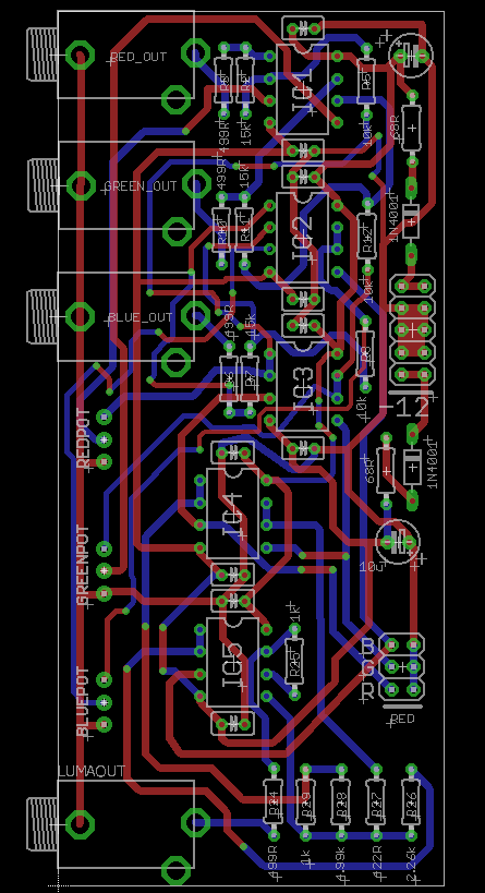
On the pcb, though, the 100nf decoupling caps should be as close to the power pins of the ICs as possible.
I think you may need to buffer the RGB inputs before putting them thru attenuverters, etc Can you probe what you’re seeing at the input nodes on the scope?
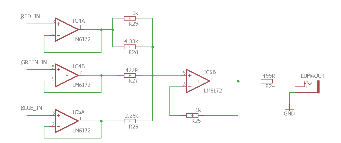
Apparently the problem was that I was testing with only one channel (R or G or B) at any given time, and the rest of the pins were “flying”. So the Luma resistors “mixer” made the signal comback from the other chanels the one connected/testing. This is not an ideal way of testing since all the time the VC will be connected and either send 0v-01v on each channel preventing this bleed.
I’ll add buffers to the inputs of the lumma and the before the attenuverters. If I only add buffers to the Attenuverters I will still get bleed from the Luma resistors-mixers. If I only add buffers to the 3 Lumma inputs I could get attenuverted signal from the feedback of path of each attenuverter.
So far the solution I like the most is to connect hte Lumma to the outputs of thf buffers RGB, that way there is no way to get it wrong. The only problem is that Lumma can get “dirty” if any cables with dirty signals (stacked) are plugged into the outputs of the expander.
So I’ve worked a bit during the weekend on the pcb, now I moved all the 104 caps near the power pins of the 6172 as suggested by @pbalj, also added buffers to everything… I wanted to make this board very cheap thats was why I tried to save on ICs, but it doesn’t make sense to save up money just for 2 more 6172.
When the time comes and everything is finished, I’ll publish the eagle and gerber files probably in my github so anyone can fab it, in any case I’ll have spares that can sell… but was wondering if anyone is interested in kits maybe I can put together maybe 10 or so. If not I’ll only sell the pcb+panel set for like 10€ or 15€ depending on the cost of the aluminium panel :). Let me know your interest with for either pcbsets or kits?