By this I guess you mean composite sync is available on the power bus, for compatibility with legacy video modules. TBC2 does not currently provide separate H or V sync outputs either at the front or rear panel, right?
As I mentioned previously, it would be super sweet to have vertical sync available as a patchable signal, for purposes of vertical interval switching, oscillator and envelope triggering, and full frame/field sample and hold. I’ve made this work with Syntonie video sync’d oscillators, and it’s awesome. But it would be even better if I didn’t have to tie up an entire oscillator and comparator just to provide vertical sync to a sample/hold trigger input.
Which also brings up the question, what is the square wave input on the front of TBC2?
Assignable trigger function input, like Memory Palace.
By this I guess you mean composite sync is available on the power bus, for compatibility with legacy video modules. TBC2 does not currently provide separate H or V sync outputs either at the front or rear panel, right?
Correct. There are no 3.5mm patchable syncs on the front or rear of TBC2.
There’s an HV ref / sync generator module coming, which will have discrete sync outputs and HV reference ramps. Unlike previous generations, a module like this isn’t required for every system, since modules like ESG3 can also function as a standalone sync generator.
The Y output is an analog sum of the RGB outputs, so addressing it individually won’t be possible. It is possible from the RGB outputs, by purposely misaligning the start of active video with the start of the sync interval. So it could be in a list of things to consider in a future firmware version, but beyond the scope of the initial release. You can get creative by syncing things off of the image loader in the meantime though. Just make a still image with the top scanline white and the rest black, and that will create a vertical reset pulse. If you do this with Red line on top, Blue line on left, then you will have some usable HV syncs out of R and B jacks.
No, not unless we included an extra/secondary Euro power header (maybe there is room.) We took a lot of care for the Euro header to only touch the internal circuit thru its 12V connection, which goes thru the EMI filter. A buffered output coming from the core board (on a separate Euro connector) might be possible. A module that is specifically a legacy sync adapter might be the right answer, for that and 14-pin sync.
ZOMG you just blew my mind. That is so clever. Too bad it ties up a whole TBC channel. With a Chromagnon and a Syntonie decoder I should be fine, though.
But the headline here is actually “RGB channels carry arbitrary information”. In the digital graphics world we use channel packed textures all the time, carrying arbitrary parameters such as roughness and metalness in stacked channels in RGB files e.g. PNG. Now I’m realizing that can be applied here.
In combination with other tools e.g. Color Wheel we can do some really creative stuff with channel mapping, color space conversion, color correction etc.
I’d love to try processing footage in hardware or software to convert to and from YUV and HSV. Maybe there is a way to make the decoder outputs and/or encoder inputs handle YUV.
Is there a limit to how many modules you can sync with one sync generator?
No limit… in Gen3 every sync node is buffered, so the transmission lines between modules should perform identically no matter how many modules are in the chain. No more loop thru weirdness woes.
Could you build a huge wall of DSG3’s synced to one ESG3?
Yep! During testing, I had 5x DSG3s and 5x ESG3s all synchronized at the same time.
Yes! Once it’s a voltage in sync with the video frame, the sky’s the limit. You could encode not just sync pulses for oscillators, but different sync patterns in an image. So “image loader” seems like a mundane feature at first glance, but in our context, it’s wildly powerful.
I was hoping to jump into the HD arena as well but have mostly Cadets and a Vidiot. I know the Vidiot is a beast that will forever roam SD land, but I was looking at the schematics for Cadet IX and Cadet IV to see whether it would be possible to cobble some HD into them or if my system would need a total upgrade.
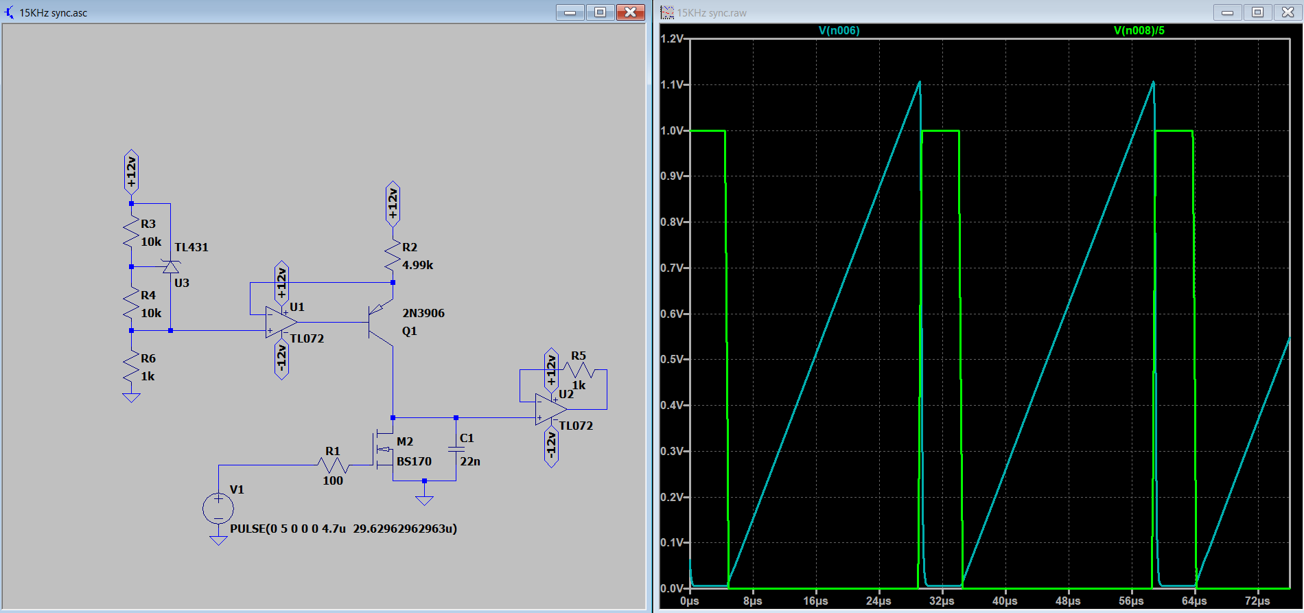
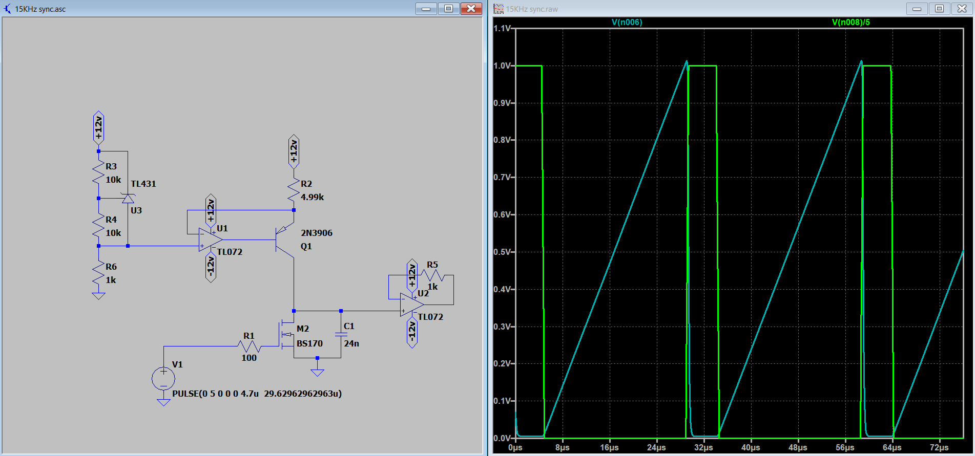
On Cadet IV, C18 and C29 could probably be swapped out for something smaller to generate the appropriately sized ramps, yes?
I think Cadet IX should be okay (unless the timing cap here is also too large), but perhaps the op-amps on the exponential converter would need to change over to something faster for HD FM inputs? I remember LM6172 not being recommended in place of the TL072s in this case – there was a better suggestion earlier in the forum I can’t recall off the top of my head.
Forgive me if this has been answered already elsewhere or if I’m barking up the wrong tree!
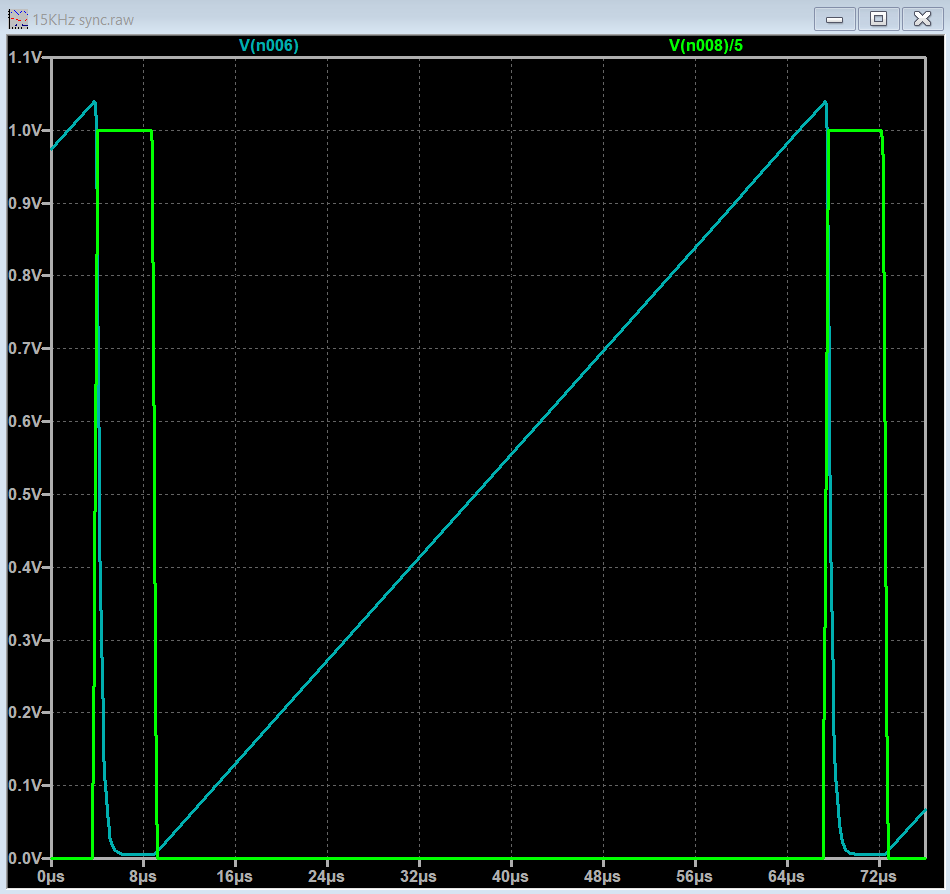
If I change the sync rate from 15.734KHz to … 33.75kHz, then a cap of about 22nF to 24nF results in close to a 1V peak. 24nF is about the highest you should use since the tolerance of any given ceramic cap might be 10- or 20% higher.
Tayda has 18nF and 22nF ceramic caps, so it should be easy to find one that fits. The trimmer, R1, should let you trim it to 1.0V even if you’re use the 18nF cap.
Changing the cap is the easy part. Getting the HD sync pulses on a 14-pin ribbon cable will be more difficult. @joem may be working on this though.
The timing cap will still work. You will just be limited by fewer bars. Changing the cap with the ratio we used above should get you fixed up.
EDIT:
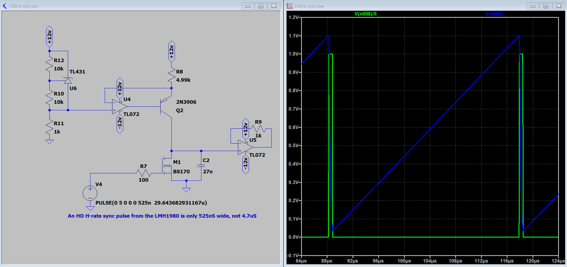
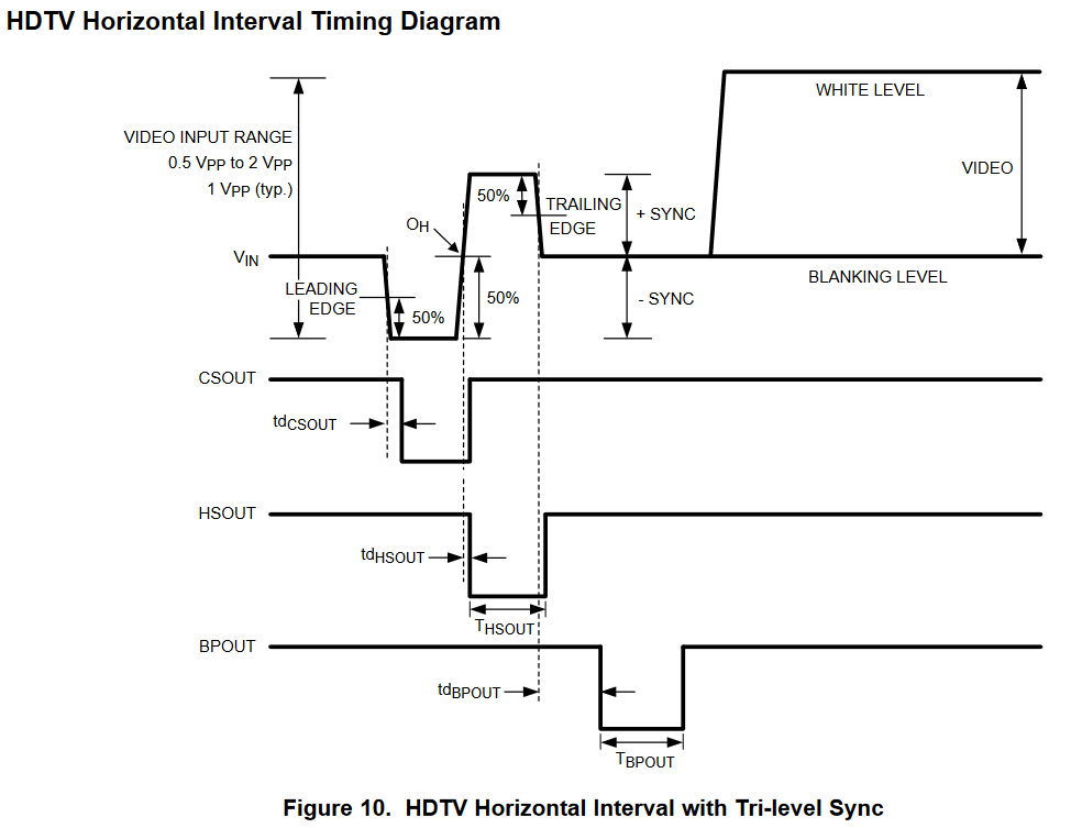
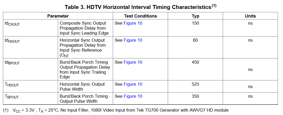
I corrected the H-rate pulse width in my simulation to 525nS as listed in the LMH1980 datasheet. This changed the perfect cap value closer to 27nF. 18nF should still work since the R1 trimmer allows for such a wide range of attenuation.
For the record, I found the LMH1980 datasheet to list tHSOUT for an HD, H-sync pulse width as 525nS, not 4.7uS as I had originally simulated. The best cap value is now 27nF. 18nF will still work since the R1 trimmer allows for such a large range of attenuation.
That 525ns is the propagation delay to expect between input and the logic outputs in the SD input modes of the LMH1980. This equates to exactly 10 clock periods of the 27 MHz pixel clock. (That’s what I have programmed as the correction factor in ESG3 firmware.) The actual HSYNC period for HD is about half of the period for SD.
A good way to do the 14 pin sync adapter would be with an embedded fpga sync generator to generate the pulses and genlock to an external source. So it could be implemented with the plugin syncgen boards from the ESG3 or the VU007B I reckon.
LMH1980 generates both HSYNC and VSYNC, and auto-detects between SD and HD, so it’s a good option if you want to integrate sync separator directly into each module.
Ah-hah. Thanks for pointing that out. 525nS sounded a bit too short, but I am still reading about the finer details of HD sync.
I am still a little confused with the LMH1980 datasheet. tdHSOUT is listed as the 60nS propagation delay and tHSOUT as the 525nS pulse output.
When considering a ramp, should the falling edge of CSOUT trigger the shorting of the cap and the rising edge of the BPOUT begin the charging phase? I was only worried about HSOUT, but tri-level sync is different than SD.