I recently built the VU008 Ramp Shifter and am having some trouble getting it to work properly and wondering if anyone could give me advice on what to try next.
The module appears to be receiving power properly, but the signals from outputs 1 and 2 are blank “all-white” images. This is the case regardless of the positions of potentiometer knobs or whether or not anything is plugged into any of the inputs.
At one point I reflowed solder and outputs 1 and 2 displayed signals that were plugged into the inputs, but they were only sifted slightly and were unresponsive to potentiometer movements and cv input. I then reflowed solder again and ever since the outputs have gone back to displaying the blank signal. Unfortunately I was not keeping track of where I was reflowing during this and was just doing so wherever connections looked questionable.
Here’s what I’ve determined so far from testing with a multimeter:
Testing at power header detects no shorts between +12v, -12v, and ground.
IN 1 and 2 without anything plugged in: 0v
OUT 1 and 2 without anything plugged into inputs: 1.48v
IN 1 and 2 with horizontal ramp plugged in from Rampes: 0.39v
OUT 1 with horizontal ramp plugged into IN 1: 1.87v
OUT 2 with horizontal ramp plugged into IN 2: 1.88v
Turning potentiometers and inputing cv do not appear to effect OUT 1 and 2 voltages
According to my research, the voltage range for Syntonie and LZX modules is generally 0-1v, so I guess the voltages output by the module, being 1.48 and above, is getting clipped resulting in the “all-white” image.
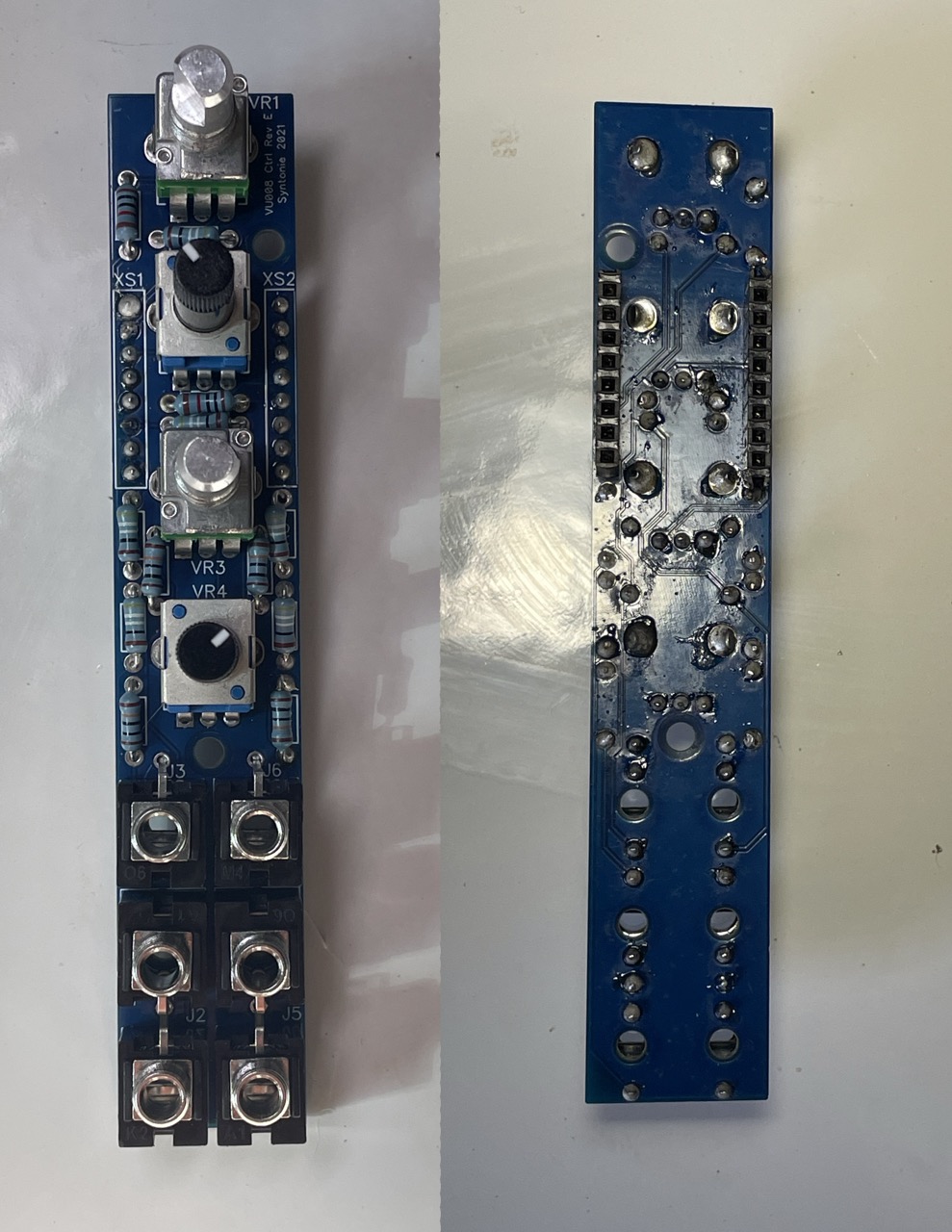
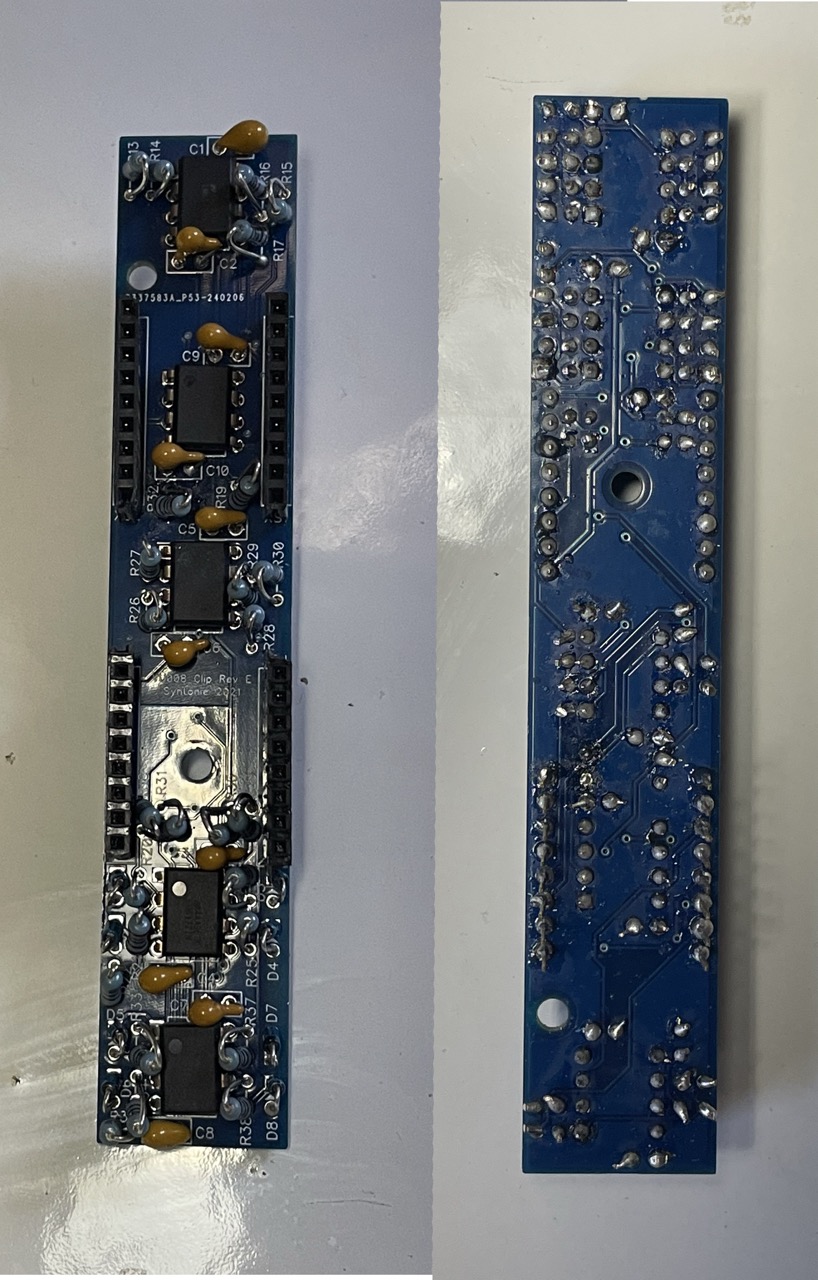
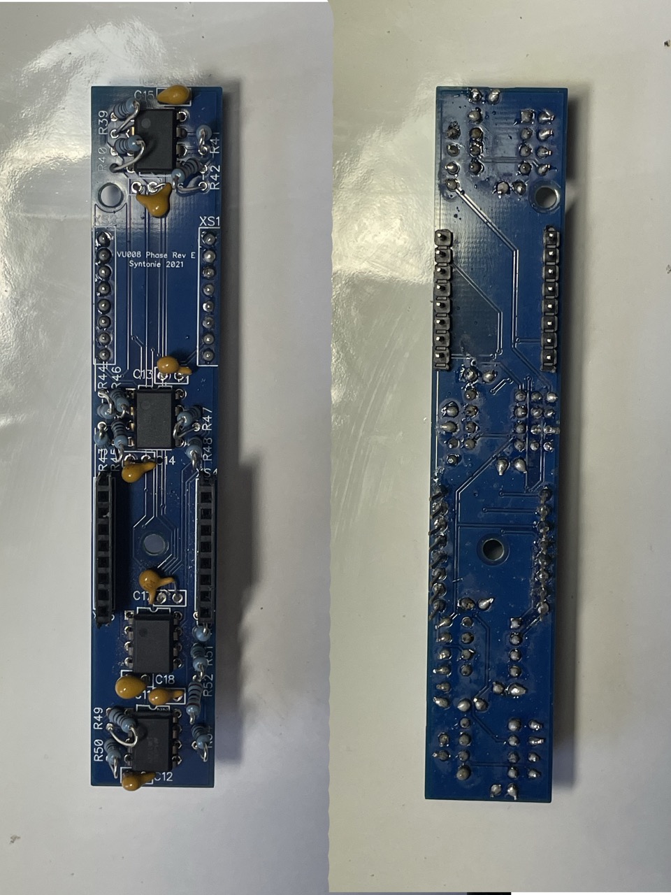
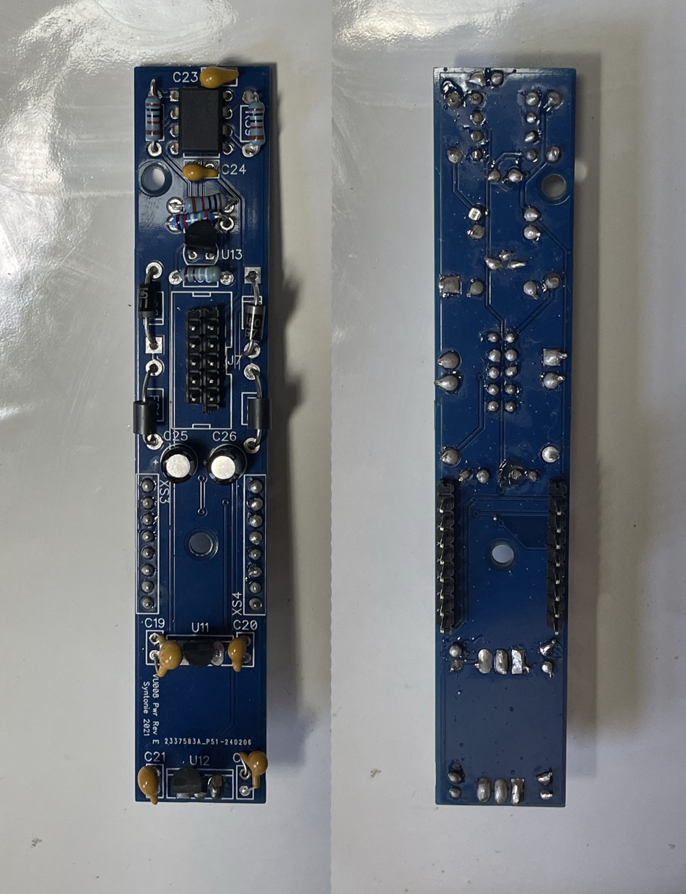
Below are images of the front and back of each board.
I’m also interested if anyone has any recommendations for businesses/individuals that repair video synth modules (preferably located in the USA) if this ends up being beyond my amateur DIY electronics abilities.
The only advice I can give visually is there are quite a few solder joints that are ‘blobbly’ and with component leads that could do with being cut shorter. My advice would be to go back and reflow all joints with a nice clean tip and some flux, then cut component leads flush to the solder joints. I’d also ensure the resistors are all bent to be uniform and vertical as they could be shorting on the nearby ICs.
One of the things to look out for is when you look at the component from above that the solder hasn’t flowed into the hole between the leg and the PCB. I can see a bunch that from above look like they have no solder at all. this probably means you haven’t heated up the PCB traces at the same time as your component, so it’s only attached to the leg.
If you don’t already leave the iron touching the trace and the component for a bit and feed the solder on to the component rather than the tip of your iron. This usually means it only starts flowing when there is enough heat transferred.
Cold solder joins are also not as conductive.
If your iron has a temp setting, you might be able to bump it up higher. Most components like resistors and caps can take a reasonable bit of heat. IC are more sensitive, but I usually leave mine around 300-350°c. I also like using a solder tip with a wider flat tip, like a screwdriver, which makes it easier to bridge the components.
Looking at your pictures, I can’t tell whether some of those upright resistors are touching the legs of the IC’s that they are next to.
One problem that I had with this module was that the header pins that connect between layers were quite thin and didn’t make a good connection inside the sockets on mine. I seem to recall that I bent them outwards a bit so that they would push outwards when they were within the socket. That got mine working.
Definitely use a meter to check the connections of the header pins between layers.
Thanks for the responses everyone! When I have a chance I’ll reflow solder again, do some more testing with the multimeter, and generally try to clean up this build.