Hi. I was just checking out the new docs site (https://lzxmodular.readthedocs.io/) and it’s nice! But I came across some confusing wording/logic on the DSG3 page, I think…
On the DSG3 page, it says:
0 represents the switch’s OFF state. 1 represents the switch’s ON state. x indicates a position irrelevant to the listed setting.
And it goes on to list settings as:
Disable Auto Detect
xxxx1xxx
Enable Auto Detect
xxxx0xxx
NTSC
0000xxxx
PAL
1000xxxx
486p5994
0100xxxx
and so on…
This could be interpreted to imply that the fifth switch is irrelevant if you’re trying to set it to a specific format, but if I’m understanding it correctly, the fifth switch actually needs to be 1 for all the listed formats. Might be a little confusing. I get that you’re trying to show that the fifth switch is what sets the auto detect enabled or disabled, but it might be clearer to get rid of the line for “disable auto detect” and just add the 1 for the fifth switch to all the formats listed.
Yes, I think this is two tables merged into one, creating the ambiguity. Please either show the 5th switch setting correctly, or seperate the two tables and make it clear that the larger table is only enabled when the 5th switch is set to 1.
My preference would be for a single table with correct settings for switch 5. This would remove the need for the reader to understand the concept of fields. While this is familiar for programmers and engineers, it may confuse other readers.
DSG3. The table on the ESG3 page is correct. Both of these could use some additional illustrations (using the DIP switch artwork from the frontpanel) in the table.
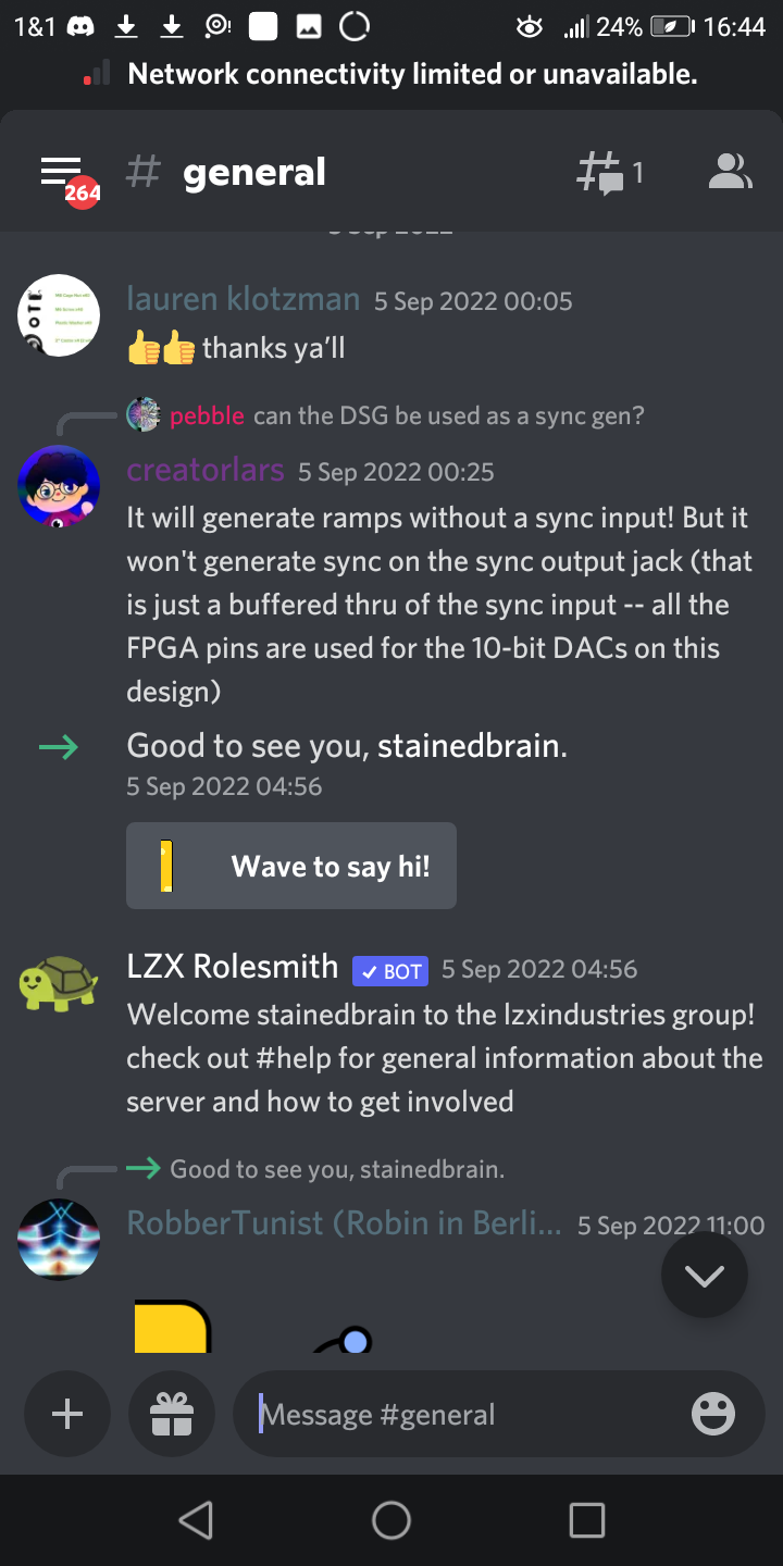
From Lars on the Discord regarding DSG3’s sync abilities. I thought it might be helpful.
“It will generate ramps without a sync input! But it won’t generate sync on the sync output jack (that is just a buffered thru of the sync input – all the FPGA pins are used for the 10-bit DACs on this design)”