Here is a quick process to trim your ESG3 module if desired. If your module’s color balance looks good to you, don’t mess with it! The purpose of the trimmers is to adjust the input range so that a 0V to 1V input scale matches the scale of the black/white level clipping on ESG3’s outputs.
- Patch a Ramp source into the Red input jack. Leave it there – the Red input is normalized to the Green and Blue jacks too, if they are left unpatched.
- Set all six control knobs to 50% Center positions.
- Monitor the Component or Composite output on your display. Zero any Contrast/Gain settings in the display’s menu.
- Engage the Mute toggles for Green and Blue channels (set toggle switches in down position.)
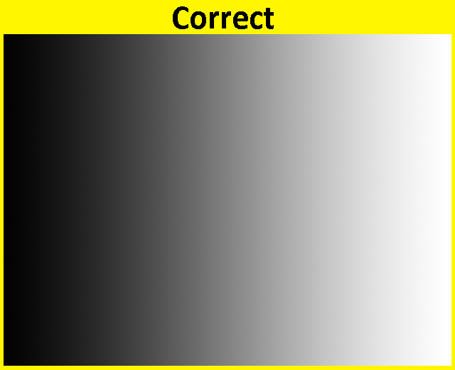
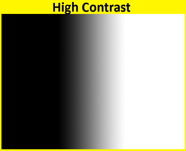
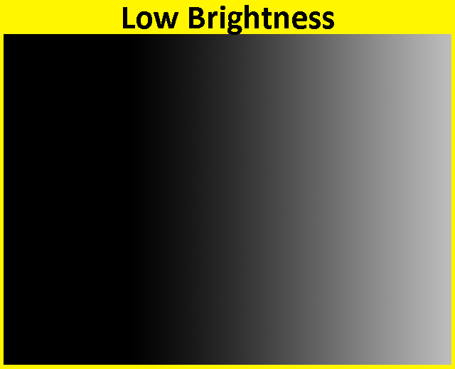
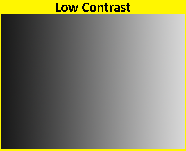
- Adjust the Red Gain & Red Brightness trimmers to maximize the range of your ramp input. When properly trimmed, the ramp signal will be 0% Red (Black) at the left edge of the screen, and 100% Red at the right edge of the screen.
- Repeat steps 3 and 4 for the other two color channels. When calibrating Green, mute Red and Blue. When Calibrating Blue, mute Red and Green.
- After adjusting each channel separately, unmute all channels. Your output should be very close to Grayscale. If there is a tint of one color channel, go back and review that channel’s calibration or make a small adjustments.
Here are some images showing correct and incorrect calibration with an input ramp source.
This content will be migrated into the docs site soon, but is posted here due to being requested. I archived some earlier threads about this issue upon posting this to aid in disambiguation and remove redundant info. Please reach out to LZX Support if you have any questions or feedback on the calibration procedure.