Video Ramps

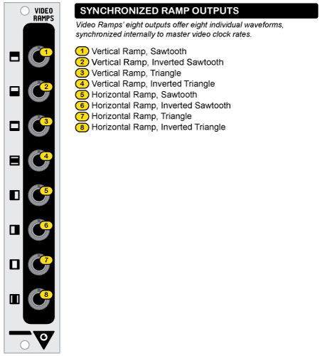
video ramps is a dual synchronized waveform generator. one ramp generator is locked to the vertical interval of the video display (field-rate sync), and the other is locked to the horizontal interval (line-rate sync). four different output waveforms are available from each ramp generator, including sawtooth, inverted sawtooth, triangle, and inverted triangle. video ramps offers a minimal solution to augment your system’s available waveform generation capabilities (such as video waveform generator modules), with outputs that are useful in almost any wipe or shape generation application. additionally, the outputs can be used to sweep the x & y inputs of an oscilloscope or vector display for vector rescanning experimentation. video ramps requires internal connection to a video sync generator module via the special provided 14-pin idc cable in order to function.
Specifications:
- width: 4hp (0.8 inches)
- mounting depth: 1.75 inches
- MSRP $169
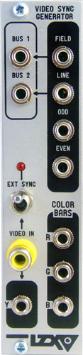
Video Sync Generator
Primary Functions
Master NTSC/PAL video sync generator with external sync lock, sync bus access, RGB color bar generator, DC-restored external video input
Video Sync Generator is one of two required modules in the LZX Visionary system, and serves as a master timing and clock generator for modules throughout a system. It’s primary companion is the Color Video Encoder, together these two modules create the framework to synthesize and process Composite video in the modular environment. In addition to a video sync signal generation, other features include access to the sync distribution buses, the creation of color bar reference signals, an external video input for external sync-locking, and a DC restored output for the Luma (Y) component of the external video signal.
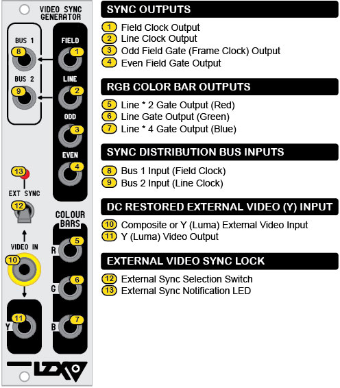
Sync Outputs
The four sync outputs on the front panel are 1V logic signals for Field rate, Line rate, Odd field rate, and Even field rate. These outputs can be used to sync Video Waveform Generator and other signal generator modules in order to create stable video patterns.
Color Bar Outputs
Color bar outputs are multiplications of the Line rate, and when patched directly to the Color Video Encoder can be used as a signal reference for calibration. They can also be used as logic signals to sync signal generators such as Video Waveform Generators. Unlike the other outputs, which are 1V signals, these are precisely adjusted to 0.75V to represent standard 75% saturation color bars.
Sync Distribution Bus Inputs
The Bus 1 & 2 input jacks allow patch access to two signal buses which allow distribution of sync signals to Video Waveform Generator modules and other modules that implement sync bus selection. By default, these buses are connected to the Field & Line outputs. By plugging into the Bus 1 & Bus 2 jacks, this connection is broken and a different signal can be inserted into the bus.
DC Restored External Video (Y) Input
Video Sync Generator’s synchronization timing can be slaved to the timing of an external video signal inserted at the Video Input RCA jack. This video signal is also DC restored, sync-stripped, Chroma notch filtered, and output via the Y output jack for processing throughout the system.
External Video Sync Lock
To lock Video Sync Generator to an external video input to the Video Input RCA jack, flip the toggle switch to a downward position. The LED will turn on solid if a valid video signal is detected, or flash if no video signal is detected. Since the sync lock feature implements a Phase Locked Loop to control the internal clock, the system defeats Macrovision protection, and in the case of a non-valid or undetected video signal, operation of Video Sync Generator is undisturbed.
Sync Output Timing
| NTSC | PAL | |
|---|---|---|
| Field | 59.94 Hz | 50 Hz |
| Line | 15.75 KHz | 15.625 KHz |
| Odd/Even Frame | 29.97 Hz | 50 Hz |
Specifications
Width: 6HP (1.2 inches)
Mounting Depth: 1.75 inches
Power Consumption: 60mA
Video Waveform Generator
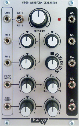
what your ear may hear as a subtle difference, your eye may see as a huge one. since the end results in video synthesis are visual: texture, pattern, and shape instead of audio, there are a number of features and controls in this vco design that take into consideration this unique application.
features:
-
wide range vco with 6 selectable frequency ranges from 30 seconds to 2mhz, coarse and fine tuning controls.
-
expanded hard sync circuit designed for accurate synchronization to video sync signals. selection switch allows normalization to sync bus signals distributed through the power header from the lzx visionary video sync generator module.
-
precision video op-amps used in all circuitry for accurate high speed frequency and waveshape modulation.
-
five simultaneous waveform outputs: triangle, sawtooth, square, pulse (rectangle) & shaped sine.
-
two independent waveshapers with cv inputs, cv attenuverters and bias controls: pulsewidth modulator & sine shaper. control pulsewidth and sine shape from 0% to 100%.
-
two frequency cv inputs with cv attenuverters. jumper-configurable options for input scaling (visionary or 1v/oct standard) and linear or exponential input.
-
attenuversion controls on all signal inputs allow attenuation and inversion of any input signal.
-
frequency notification led.
-
no external +5v power rail necessary, user configurable jumper allows selection between onboard +5v regulator or +5v rail on standard power header.
Specifications:
- width: 16hp
- maximum current draw: 140ma
- MSRP $399
Voltage Bridge
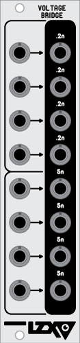
voltage bridge is a simple, straightforward 8-channel voltage scaling module designed for conveniently interfacing with synthesizer modules and devices outside of or integrated into an lzx visionary system. four sets of inputs/outputs attenuate a signal by 20% (5 volt scale to 1 volt scale), and another four sets of inputs/outputs increase the gain of a signal by 500% (1 volt to 5 volt scale.) this module can be used for any type of signal: audio, control voltage, logic, video, etc. aside from its utility purposes, it can be used to achieve various effects as well.
Specifications:
- width: 6hp (1.2 inches)
- mounting depth: 1.25 inches
- MSRP $99
Voltage Interface I
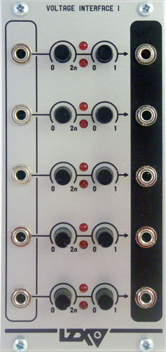
the voltage interface i is a 5-channel precision voltage conditioner which can transform external signals, from 10v control voltages to line level audio, into the 1v signal ranges expected by lzx visionary modules. an external signal is inserted into an input on the left side of the module. gain and bias controls are adjusted until neither of the two clipping indicator leds are lighting up. internal clipping circuitry for each channel ensures that output voltages above 1v and below 0v are completely clipped off. the conditioned signal is accessible at the output jack on the right side of the module.
Patching Tips
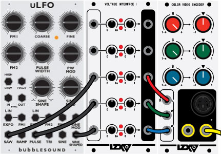
LZX Visionary modules can receive 10V signals from standard EuroRack audio and CV modules, however they expect a voltage range of 1V in order to get optimum operation out of the module controls and high bandwidth circuitry. In some cases, it won’t matter — but in others, the Voltage Interface I (VI1) module can be used to convert external voltages to the correct range. In this patch, three waveform outputs from the Bubblesound uLFO are patched into input channels on the VI1. The VI1 gain and bias controls are adjusted so that the two clipping notification LEDs are NOT lighting up at any point. The VI1 outputs are then fed straight into the Color Video Encoder to create a morphing, voltage controlled color field.
Specifications:
- width: 12hp
- maximum current draw: 85ma
- MSRP $199
XY Display Driver
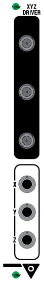
Primary Functions: interfacing with oscilloscopes and XY displays.
SPECIFICATIONS
- Status: Special Order
- Width: 4HP
- Mounting Depth: 2 inches
- LZX Sync Cable Required