LZX VISIONARY: AN INTRODUCTION
In today’s era of digital video and computer graphics, tools for the video artist wishing to experiment with the use of analogue circuitry for the creation and processing of images have largely been lost, left to a rich tradition of video artists from the 1960′s and 1970′s. We believe the past several years’ renaissance in the use of analogue synthesizers in music production, and the effectiveness of integrated analogue and digital workflows, to be a precursor to a similar renaissance in video technologies. There is a warmth and immediacy in the analogue, hardware-based video workflow which is lacking within software environments, and video artists worldwide have long been frustrated by lack of access to such tools outside of a few scattered studios. With LZX Visionary, it is our goal to both reintroduce classic vintage video processing and synthesis circuitry, and continually push development of new tools which enhance integration with the tools of the day and fulfill the needs of the modern video artist.
LZX Visionary is a line of EuroRack format synthesizer modules designed for creating and manipulating video and images. While our modules may be augmented within the same system by a wealth of interesting modules from other manufacturers intended for the creation of audio, our goal is to offer a complete system specifically designed for the demands of generating and processing video signals.
WHAT IS MODULAR VIDEO SYNTHESIS?
A modular synthesizer is a type of analogue computer which is programmed by connecting the inputs and outputs of various functional modules to each other, typically in order to produce or process audio signals. The advantages of a modular synthesizer are its expandability and flexibility, since a system can be designed around goals the user wishes to achieve, and easily reconfigured (or patched ) for multiple uses. Video synthesis is another application of the modular synthesizer, and while the application is different, the same principles of analogue signal paths and voltage-controlled parameters still apply.
While many functional modules are useful for both audio and video, some new module designs must be introduced which deal with the special requirements of video signals. The LZX Visionary modular video synthesizer can function as a traditional video mixer, keyer, or special effects unit, or delve into experimental territory such as the creation of abstract patterns with voltage-controlled oscillators, complex color space modulation, audiovisualization, and many as yet to be discovered techniques.
OUR APPROACH
- All signals within the system are 1 Volt, DC-coupled voltages regardless of frequency range or signal type.
- All signal inputs can accept signals from all signal outputs.
- All inputs are capable of wide bandwidth response and processing of signals up to high frequency video rates.
- Video input and output to the system are handled by specific modules, therefore most signal generation and processing modules remain functionally independent of any specific video format.
- Video signal paths within the system exist as triple colorspace (RGB, YUV, etc) or monochrome signals, with sync and subcarrier insertion and DC restoration occuring only at external video input and video output modules.
- Modules are designed with functional density and complete patchability as primary goals. As a result, the system is designed with the exploration of complex signal paths and creative interpretation in mind rather than instant gratification.
Videos
8 Stage Video Quantizer and Sequencer
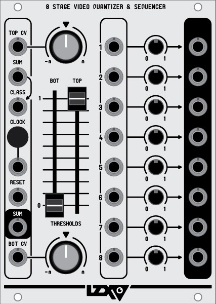
primary functions: amplitude classification, sequential multiplexing
8 stage video quantizer & sequencer is a complex key generation and high speed switching module. it consists of eight high speed analogue switches, only one of which is active at any time. each switch has an independent input and output, along with a bias control which is summed with the input. there is also a global sum input which feeds a signal to the inputs of all eight switches, and a global sum output which shows the output of the currently selected switch.
the quantizer takes whatever signal is input to the classify input and splits it into eight amplitude bands distributed evenly between upper and lower threshold points. the upper and lower threshold voltages also have control voltage inputs and attenuverting controls for modulation. the output of the quantizer is a number between 0 and 7.
the sequential clock also has eight steps from 0 to 7 and functions separately from the quantizer. when a clock pulse is received, the sequential clock counts upward by one. when a reset pulse is received, the clock resets to a value of 0.
the values of the quantizer and sequencer are summed together and wrapped around, the value of this sum determines which of the eight video switches is currently active. for example, if both the quantizer and sequencer have a current value of 0, then the selected switch is also 0 (0+0=0), which is the first switch. if the value of the quantizer is 2, and the value of the sequencer is 7, then the sum wraps around and the currently selected switch is the second switch (7+2=9, 9-8=1.)
Specifications:
- width: 18hp
- mounting depth: 1.75 inches:
- lzx sync cable required? no
- MSRP $599
Audio Frequency Decoder
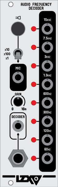
audio frequency decoder is an eight channel audio envelope extraction tool useful for audiovisualization and other techniques. an audio source is derived either via the module’s internal electret microphone and preamp, or an external source from inside or outside your video synthesis system. the gain control sets the overall level of the audio signal.
once the audio source is selected and gain level set, audio is split through eight bandpass filters spread out across the audio frequency spectrum. each of these bandpass filters then passes through an envelope extractor followed by an additional low pass filter. the resulting eight outputs are control voltages which represent the amplitude of each frequency band of the original audio signal, and may be patched to control parameters in the video synthesis system to create complex moving animations which respond accurately to the frequency content of the original audio signal.
Specifications
- width: 8hp
- mounting depth: 1.75 inches
- lzx sync cable required? no
- MSRP $249
Color Time Base Corrector
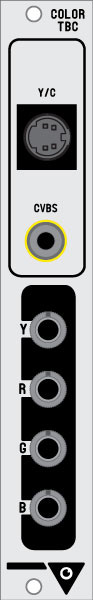
color time base corrector (tbc) is a core module for external video input into the lzx visionary system. in order to mix multiple video sources together within the system, each source must be running in synchronization with the others. additionally, ntsc/pal sources must be decoded into color and luminance channels (yrgb) for patching and manipulation inside the video synthesizer. this module provides these functions cleanly and easily: video goes in via the s-video or composite input jacks, and the yrgb outputs are available for further processing. the number of simultaneous external video inputs to your lzx system is limited only by the number of tbc modules.
specifications:
- width: 4hp
- mounting depth: 3.5 inches
- lzx sync cable required? yes
- MSRP $379
Color Video Encoder
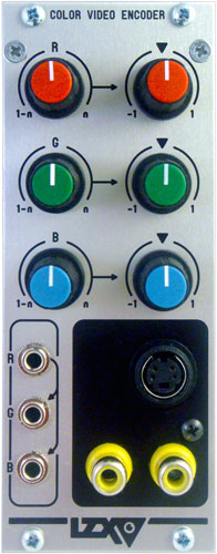
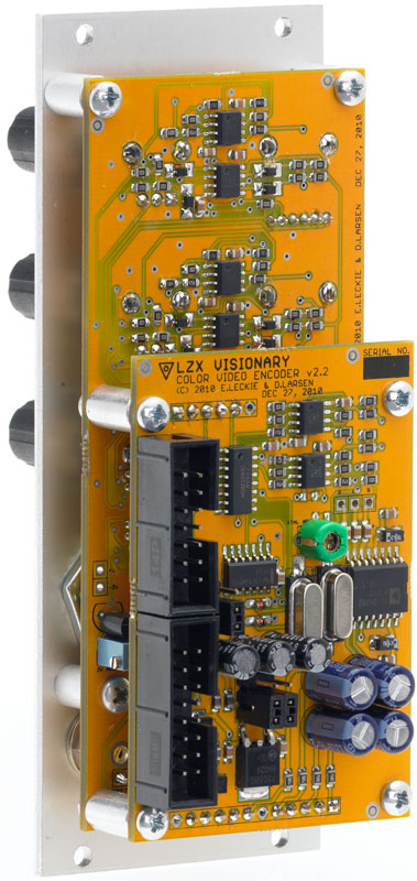
unlike audio, a video signal requires special information to be encoded into it in order to be displayed or recorded. synchronization signals tell the target device when to display a new frame or a new line. in addition, it’s important that the signals which create the chroma (color) and luminance (brightness) information are within the valid ranges allowed according to video standards.
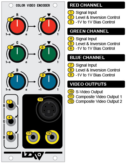
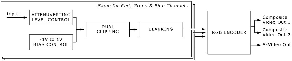
the color video encoder (cve) module is one of two required modules in the lzx visionary system. the cve performs the function of taking signals from three separate color input channels: red, green & blue, conditioning and encoding them so that you always see valid yuv output video in composite and s-video formats. any input signal between 0 and 1 volts becomes viewable video, while the rest is safely clipped off.
color channel inputs:
for each color channel, a bias control allows you to adjust the relative amount of this color that is added or subtracted from the input signal, and for each input an attenuverter allows you to adjust the level and inversion of the input signal. while inverting the signal by turning the attenuverter knob counter-clockwise from its center position, a positive 1v bias is also added to the signal. the inverted input signal is subtracted from 1v, which ensures the input signal is still within the 0-1v viewable range.
input normalization:
to simplify patching workflow, the green & blue channel inputs are automatically connected to the red input. this connection to red is broken when a plug is inserted into the green & blue jacks. this switched structure allows you to send a single input signal into the red input instead of using extra cables and a multiple to send the same signal to all three.
video sync generator connection: the cve requires master synchronization signals from the video sync generator module, which are passed by a special 14-pin sync cable. care must be taken that this connection is made correctly, or else the module will not function. further information can be found on the module installation page.
video outputs:
the cve can easily be configured to produce valid video output for both pal and ntsc formats by repositioning a jumper on the circuit board. you can install as many cve modules in your lzx visionary system as you like all of which can derive synchronization signals from a single video sync generator module. the cve has three video outputs, two composite and one s-video. the multiple signals are useful for situations in which you want to send one signal to a preview monitor and another to a projector or recording device.
specifications:
- width: 10hp
- maximum current draw: 100ma
- MSRP $379
Colorspace Mapper
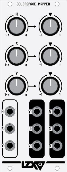
colorspace mapper is a complex color mixing and processing tool based on the conversion from hsy (hue/saturation/brightness) to yuv (brightness/red-y/blue-y) and rgb (red/green/blue) triple colorspaces. it includes several internal voltage controlled amplifiers, polar-to-cartesian coordinate waveshapers, input processors and summing circuits. all signal paths are suitable for wide bandwidth, video-rate processing.
external inputs may be patched into the hsy inputs on the frontpanel. these inputs are then processed by their associated gain/inversion controls and summed with their associated bias controls. the resulting hsy signals are then fed into the hsy-to-yuv conversion circuitry and output to the yuv jacks. the yuv signals are simultaneously fed into a yuv-to-rgb conversion matrix and output to the rgb output jacks. very powerful colorization and conversion can occur by remapping external signals to these alternate colorspaces. for example, a black and white video fed into the hue input, will cause the output colorspace to achieve a hue rotation, or thermal imaging type of effect.
the hue-to-uv waveshaper has a depth of 720 degrees (2 full rotations.)
Specifications
- width: 10hp
- mounting depth: 1.75 inches
- power consumption +12v: 105ma
- power consumption -12v: 105ma
- lzx sync cable required? no
- MSRP $399
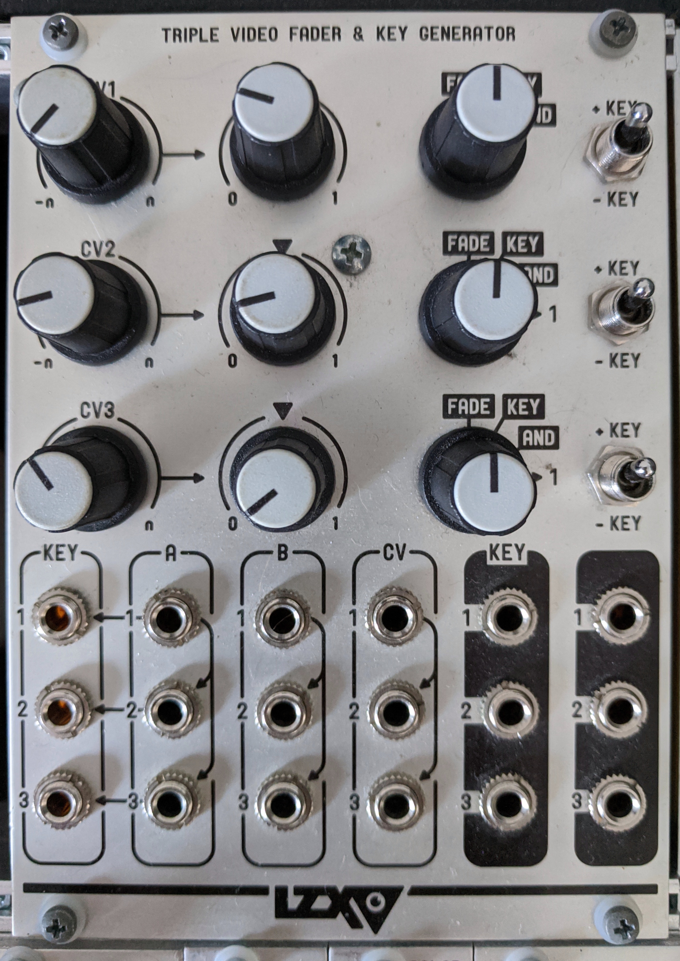
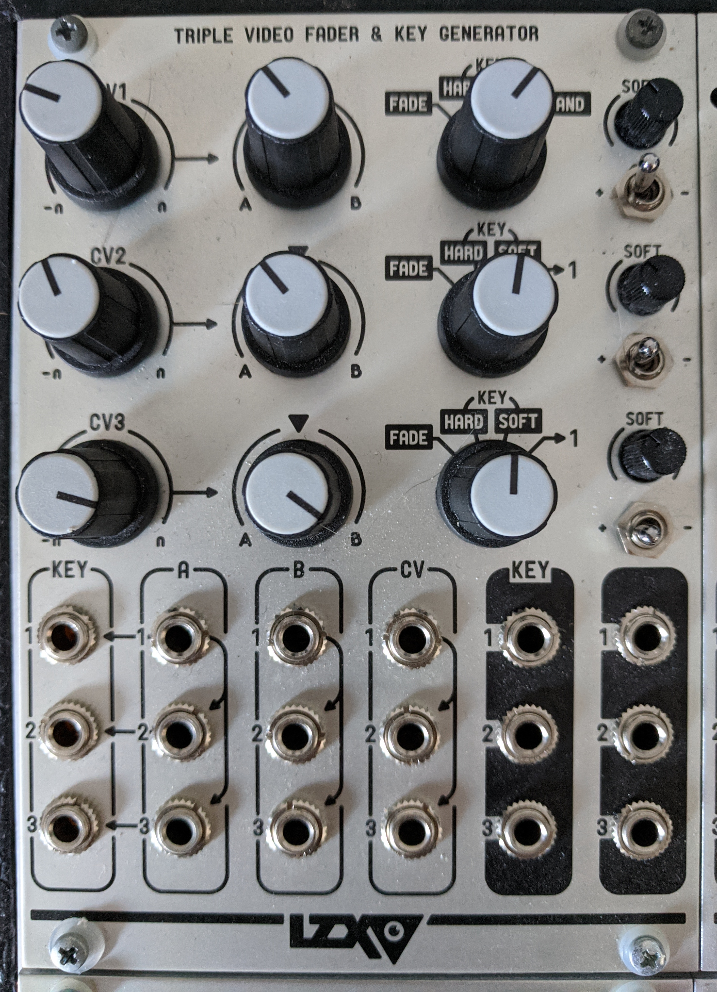
Triple Video Fader & Key Generator
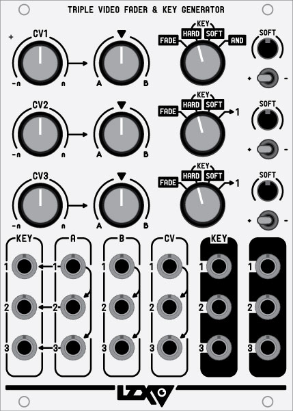
the triple video fader & key generator (tvf) is a versatile signal processing module which includes three separate voltage-controlled crossfaders and three separate voltage comparators (key generators). cascaded input columns and selectable crossfader control source modes allow complex operation for a variety of purposes such as crossfading, multiplication, luma keying, chroma keying, window comparison, simple comparison and amplitude classification.
control voltage inputs and bias controls:
control voltage (cv) inputs have corresponding level/inversion controls, allowing both addition or subtraction of the input signal from the additional 1v bias controls. once the cv input and bias level are summed, they control the key generator’s comparator threshold. depending on the crossfader control source mode, they may also directly control the corresponding crossfader.
faders:
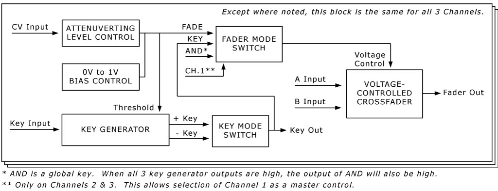
signal inputs to a and b channels of the voltage-controlled crossfaders are accessible via the frontpanel. mode switches allow selection of the control voltage source for the crossfaders. the fade mode enables the summed cv & bias voltages to control the crossfader directly. the key mode enables the the corresponding key generator output to control the crossfader directly. the and mode enables a logical and generated from all three key generators to control the crossfader directly. in addition, crossfaders 2 & 3 can select crossfader 1’s control source for use as a master control. crossfader outputs are accessible on the right side of the frontpanel.
Voltage-controlled crossfader with two inputs and one output. When control source is at 0 Volt, channel A is completely on. When control source is at 1 Volt, channel B is completely on. Voltage levels between 0 Volt and 1 Volt represent a proportional mix of channels A & B. With signal inserted to channel B only, the fader behaves as a traditional voltage-controlled amplifier.
KEY GENERATOR
High speed voltage comparator serving as a key generation source. When the key generator input is greater than the voltage represented by the sum of the CV input and bias controls, the key output is 1 Volt (on). Otherwise, the output is 0 Volt (off). Inversion switches select between non-inverted and inverted versions of this logic signal.
CONTROL SOURCE
Control voltage (CV) inputs are processed by level and inversion controls and then summed with a variable 0 to 1 Volt bias. This sum serves as the threshold level for the key Generator, and as the control source for the fader while in FADE mode.
PATCHING TECHNIQUES:
Single Threshold Comparator
Insert a signal into any key input. Associated 0 to 1 Volt bias control determines the voltage threshold for the key signal appearing at the associated key output. Key inversion toggle switch can select positive or negative logic. In positive mode, key output will be 1 Volt when the Key signal is higher than the threshold level. In negative mode, key output will be 1 Volt when the Key signal is lower than the threshold level. Another signal can be inserted to the associated Control Voltage (CV) input, and the associated level and inversion control adjusts the amount the external signal adds to the keying threshold.
Multiplier/VCA (voltage controlled amplifier)
Insert any signal into B input of a fader channel. Switch associated fader control source switch to FADE. Amplitude of the input signal is then controlled by the sum of the 0 to 1 Volt bias control and any signal input to the CV input. This can be used to multiply two video signals together, or as an automated fader.
Automated Crossfading
Insert any two signals into A & B inputs of a fader channel. Switch associated fader control source switch to FADE. Associated 0 to 1 Volt bias control determines the proportional mix between A & B inputs appearing at the fader output. When bias control is at 0 Volts, channel A will be 100% amplitude, with channel B at 0%. When bias control is at 1 Volt, the opposite is true. Another input signal can be inserted to the associated Control Voltage (CV) input, and the associated level and inversion control adjusts the amount this signal adds to the bias. In this way, a low frequency modulation signal can be used to smoothly fade between the two signals.
Luma Keying
Patch up the single threshold comparator patch as described above, but take the output from fader output instead of key output. Insert the input signal to A channel input (which will be automatically be connected to the associated Key input.) Switch the associated fader control source mode switch to KEY. Now the input signal will be keyed in and out based on its own brightness level. A second signal can be inserted to “B” channel to switch between two sources.
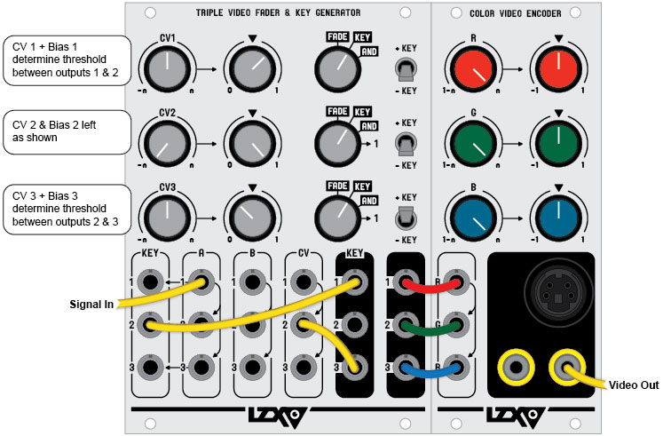
RGB Fader
This patch uses all three channels to fade between two RGB signals. Configure the automated crossfading patch as described above, sending red, green & blue signals to A & B inputs of all three channels. Switch channels 2 & 3 to ->1 mode in order to select channel 1 as the master control source. Chanel 1?s CV & Bias controls will now identically control crossfading between all faders.
Window Comparator
This patch uses two channels together in order to generate a single key or switched signal with an upper and lower threshold. First, patch up the luma keying patch as described above, and patch the fader output of this patch to the key input of a second channel’s key input. Switch key inversion toggles on either channel to opposite positions and adjust key thresholds appropriately. Bias controls and CV inputs can modulate upper and lower thresholds separately. Additional note: If desired, the patch can be expanded to control “width” and “position” instead of upper and lower thresholds by using a third channel as a VCA to control the gain of the incoming modulation signal, which can then be applied equally to the two upper and lower thresholds.
Chroma Keying
Set up RGB fading patch as described above, but switch channel 1 to AND mode. Boas controls, key inversions and CV inputs on all three channels now determine the amount each color of channel A contributes to the Chroma key switching logic. With time spent finding the desired settings, any specific range of color can be targeted as the key source in variable degrees.
3-Band Amplitude Classifier
An amplitude classifier splits an input signal into different amplitude ranges and is useful for colorizer patches where you want control over the shared points between multiple bands rather than independently variable comparators. This patch uses all three channels. Switch all channels to Key mode. Switch channels 1 & 2 to -Key, and channel 3 to +Key. Insert signal source to A1 jack. Patch Key1 Out to Key2 In. Patch Key3 Out to CV2 In. Turn CV2 control fully counter-clockwise. Turn channel 2 bias control fully clockwise. Ensure that Bias1 is higher than Bias3. Now fader outs and key outs represent three split amplitude bands, with channels 1 & 2 controls and CV inputs representing the threshold points between bands 1 & 2, and bands 2 & 3.
Cascaded Crossfaders
Since each of the there CV crossfaders can function independently, they can be used to create several types of voltage-controlled signal mixes. One method is to take the outputs of crossfaders 1 & 2 and send them to the A & B inputs of crossfader 3. Up to four signals can be input to crossfaders 1 & 2 inputs, and crossfader 3 is used to crossfade between the outputs of the first two.
Max/Min Selector
This patch compares two input signals, and outputs whichever one is highest (max) or lowest (min) at that point in time. It can be replicated on all 3 channels to work on two triple colorspace (RGB) signals, or cascaded to multiple channels to add additional signals to the max/min selection. Input signal #1 to A input (which gets automatically connected to corresponding Key input). Input signal #2 to B input, and use a mult or stacking cable to send this same signal to corresponding CV input. Set CV control fully CW. Set bias control fully CCW. Set channel mode to “Key”. Positive logic selects “Min” response, negative logic selects “Max” response. Fader output jack represents the Max/Min selection.
Voltage Controlled Panner
A panner allows variable gain of 1 input signal to 2 separate outputs (as opposed to a crossfader, which allows variable gain of 2 input signals to 1 output.) This patch uses two channels of the TVF&KG. Input signal to B1 input (it will consequently be connected via switched jack to B2 input). Input CV source to CV1 input (which will consequently be connected via switched jack ot CV2 input.) Turn CV1 fully CW. Turn Bias 1 fully CCW. Turn CV2 fully CCW. Turn Bias 2 fully CW. Input signal will be panned between fader outputs #1 and #2 based on the external control voltage source.
key generators:
the key generators are voltage comparators which generate a logical 1v signal when one input is higher than the other. signal inputs to the key generators are accessible via the frontpanel. key inputs are by default connected to corresponding a channel fader inputs via switched jacks. in a traditional video keying arrangement, this means the key source can be derived from either the a channel video, or from a separate source patched into the key inputs as a mask. there are inversion toggle switches to select a positive or negative key output. direct outputs for the key generator are accessible on the frontpanel.
specifications:
- width: 16hp
- maximum current draw: 135ma
- MSRP $499
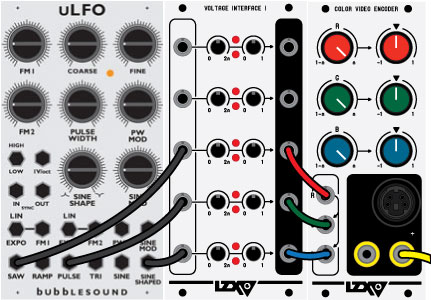
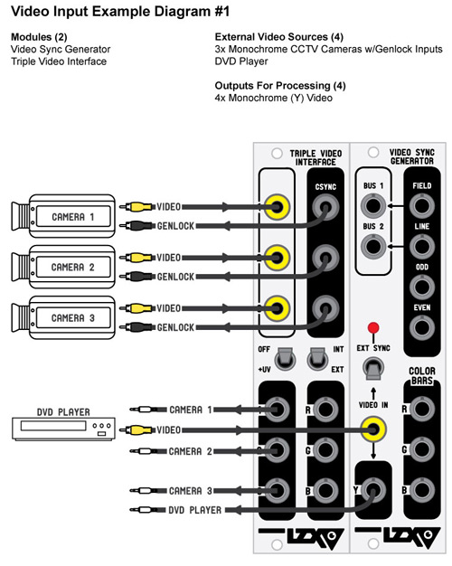
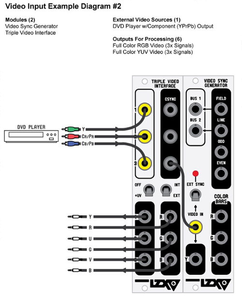
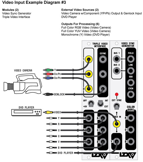
Triple Video Interface
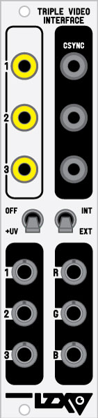
triple video interface is a wideband analogue input module for external video sources and serves multiple use cases. input sources are dc restored, sync clipped, and scaled to proper voltage levels before output for processing and patching throughout an lzx visionary video synthesis system. in addition, three composite sync outputs can be used to feed genlock inputs on external devices for synchronizing purposes. also included is a yuv to rgb colorspace converter - with this feature, an external component (yprpb source) can be translated to the rgb colorspace internally.
please be aware that this module does not include time base correction, frame synchronization, or composite color decoding features. if those features are required, you will need the color time base corrector module.
please note: this module requires connection to the video sync generator by means of a video sync distribution chain cable which must be purchased separately.
external video input example diagrams
Specifications
- width: 6hp
- mounting depth: 1.75 inches
- lzx sync cable required? yes
- MSRP $279
Triple Video Multimode Filter
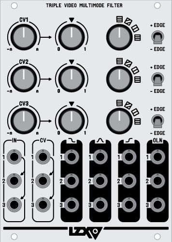
voltage-controlled filtering, edge and outline extraction, image softening and blur
Specifications:
- width: 18hp (3.6 inches)
- mounting depth: 1.25 inches
- MSRP $549
Triple Video Processor
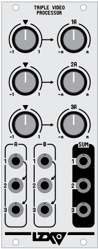
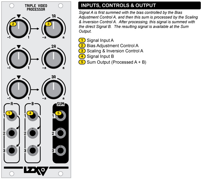
the triple video processor is a wide bandwith signal processor suitable for adjusting the gain and bias of three simultaneously processed signals, while also allowing secondary signals to be summed into the final output mix. triple video processor was designed specifically to address common use case scenarios within the video synthesis system. since the bias is applied to the input signal before its scaling & inversion control, the cross-over point at which the signal is inverted can be adjusted, enabling bi-polar voltage mixing when the signal is summed with the b input channel.
Specifications:
- width: 10hp (2 inches)
- mounting depth: 1.25 inches
- bandwidth: 40mh
- MSRP $199
Video Blending Matrix
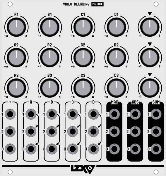
the video blending matrix is a versatile signal processing module used for mixing input signals in various mathematical input and output modes. cascaded input columns allow each of the vbm’s three 5-channel dc mixers to operate either independently or combined in various input matrix configurations.
signal inputs:
each mixer has five dc-coupled signal inputs which can be used for any type of signal, from low frequency modulation to full bandwidth video. four have associated level/inversion controls and inversion mode switches, the remaining one is a direct summing input for chained operation between multiple vbm modules. with the combination of the level/inversion control and inversion mode switches, three different variable input functions are possible: addition, subtraction, and inverted addition. with no signal input, each control can function as a variable 1v bias control.
mix outputs:
two separate mix output functions are available for each mixer: sum and absolute. the sum output is the sum of all input signals. the absolute output is the absolute value of the sum (negative signals are inverted and become positive.) the absolute outputs enable techniques such as frequency multiplication and the creation of solarization and color difference effects.
matrix operation:
matrix configuration is achieved through the normalization of input columns between the three independent signal mixers. with a single signal patched into the topmost input of mixer 1, this signal is applied to the corresponding input on mixers 2 & 3. within a patch utilizing triple colorspace (such as red, green, and blue channels), this feature allows a single signal to be mixed in varying amounts to each channel.
Specifications:
- width: 22hp
- maximum current draw: 220ma
- MSRP $599
Video Divisions
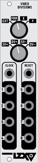
video divisions is a high speed digital logic processing module with several complex modes for generating horizontal and vertical bars, and dividing other signals. it is capable of processing signals throughout the video bandwidth. each of the two inputs includes a high speed comparator which converts any input signal into key logic around a threshold of 0.5 volts. as with all modules in the lzx visionary line, the inputs can therefore receive any type of signal not just binary logic pulses.
please note: this module requires connection to the video sync generator by means of a video sync distribution chain cable which must be purchased separately.
video divisions includes four preset modes and four count modes.
ext mode
in ext mode, the eight outputs represent eight divisions of an input signal put into the clock input. the current count is reset via a pulse at the reset input. when in sq+ count mode, the outputs count one after the other in a ring, so that only 1 output is high at any time. this function is similar to a gate sequencer. in dv+ count mode, the outputs represent binary divisions /2, /4, /8, /16, /32, /64, /128, /256. while in ext mode, the sq- and dv- modes are identical to sq+ and dv+, except that the input clock is blanked so that clock pulses outside the viewable area of the screen are ignored. this is useful for correcting glitches in horizontal patterns.
frm mode
in frm mode, the eight outputs represent divisions of the system’s frame rate clock. the count is reset via a pulse at the reset input. when in sq+/sq- count modes, the outputs count one after the other in a ring, so that only 1 output is high at any time. this function is similar to a gate sequencer. in dv+/dv- count mode, the outputs represent binary divisions /2, /4, /8, /16, /32, /64, /128, /256.
x mode
in x mode, the eight outputs produce vertical bars. the clock and reset inputs control a secondary counter which offsets the primary counter, to achieve modulation. when in sq+/sq- count modes, the outputs count one after the other in a ring, so that only 1 output is high at any time. this function is similar to a gate sequencer. in dv+/dv- count mode, the outputs represent binary divisions /2, /4, /8, /16, /32, /64, /128, /256. in sq+/dv+ modes, the secondary counter shifts the vertical bars to the right. in sq-/dv- modes, the secondary counter shifts the vertical bars to the left.
y mode
y mode is identical to x mode, except horizontal instead of vertical bars are produced by the outputs.
please note: this module requires connection to the video sync generator by means of a video sync distribution chain cable which must be purchased separately.
Specifications:
- width: 6hp
- mounting depth: 1.75 inches
- lzx sync cable required? yes
- MSRP $269
Video Flip Flops
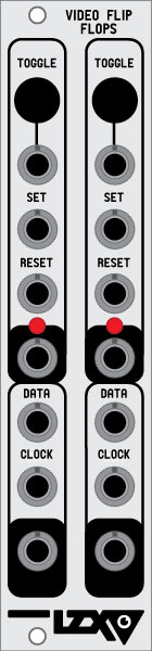
video flip flops is a high speed digital logic processing module with four single bit digital memory functions. it is capable of processing signals throughout the video bandwidth. each of the ten inputs includes a high speed comparator which converts any input signal into key logic around a threshold of 0.5 volts. as with all modules in the lzx visionary line, the inputs can therefore receive any type of signal not just binary logic pulses.
there are two identical channels arranged in columns. each column contains two flip flops. the first flipflop is a toggle flipflop with toggle, set, and reset inputs. a positive pulse on the set input will switch the output high. a positive pulse on the reset input will switch the output low. a positive pulse (or button press) on the toggle input will invert the current value of the output. below the toggle flipflop is a data flipflop. the data flipflop will transfer the value of the data input to the output, whenever a positive pulse is received at the clock input jack.
the toggle flipflop is very useful for complex shape processing and combinations of key signals. the data flip flop is useful for quantization of input data, forcing the input to only update in time with the secondary clock signal.
Specifications:
- width: 6hp
- mounting depth: 1.75 inches
- lzx sync cable required? no
- MSRP $219
Video Logic
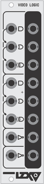
video logic is a high speed digital logic processing module with multiple boolean and inversion functions. it is capable of logical combinations of video rate signals throughout the video bandwidth. each of the eight inputs includes a high speed comparator which converts any input signal into key logic around a threshold of 0.5 volts. as with all modules in the lzx visionary line, the inputs can therefore receive any type of signal not just binary logic pulses.
there are two boolean functional blocks with 3 inputs and 3 outputs each. the outputs represent the logical and, or and xor combinations of the 3 inputs signals. additionally, there are two inverter functions. the output of these inverters represents the logical inversion of the input signal. through patching some signals to the inverters before the boolean functions, nand, nor and xnor logic functions are made possible.
Specifications:
- width: 6hp
- mounting depth: 1.75 inches
- lzx sync cable required? no
- MSRP $219