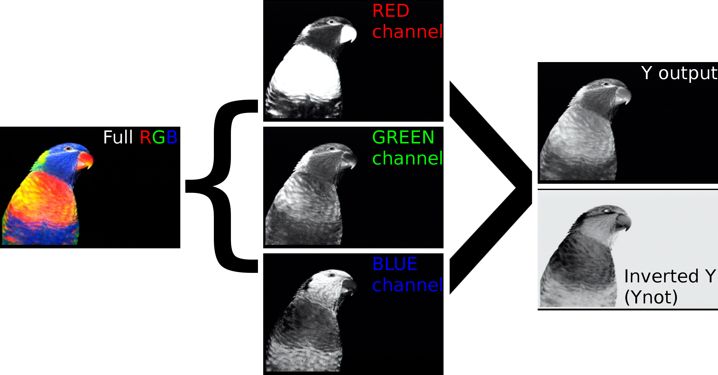
LUMA (aka: and y not) converts an RGB image into the greyscale equivalent Y. Y is the specially weighted mix of R, G and B that accurately represents the luminance intensities of each color as they are perceived by the human eye according to the “International Telecommunication Union Recommendation (ITU-R) “BT.601.”
Much like B&W TV.
Y is an important signal for patching because neither Red, Green nor Blue alone can accurately represent a full color image’s perceived brightness levels. Consider the differences in this example:
You may recognize the term on LZX’s Memory Palace, CTBC, the forthcoming TBC2, and Visual Cortex (as Luma), etc., but this gives you the same function in a minimal 4HP package and it can be applied to any RGB set – not just hardwired to an input amp, for instance.
tl;dr Users may now get Y from any arbitrary RGB set they choose. LUMA also buffers the original RGB inputs and offers an inverted Y.
This is the first module I will be offering in the usual DIY version as well as a preassembled SMD version which is shallower for skiff users. Either version is functionally identical.
DIY PCB/panel orders include circuit boards and faceplate only, users must source components listed in the BOM below.
Built modules are personally assembled, cleaned and tested. Each include a 6" 10-16 pin power ribbon cable. In this case, built modules are assembled surface mount boards with a depth of only 32mm (max) including the ribbon cable with stress relief clip.
In every example below, an RGB pattern goes into Luma to create Y that’s fed into the source inputs of keyers (Doorway) that go into the shared CV inputs of triple faders (Marble Index). This patch technique lets you cleanly create an adjustable soft mask that is directly related to the luminance of one side of your triple fader’s RGB inputs. In most of these patches, the other side of the triple fader is set to black and Y is being used to create more black negative space by constraining the fader’s output around the true overall brightness of an abstract pattern’s shape.
Another useful patch scenario is to use it as a way to mix down a RGB signal right before your video encoder so you can feed the relative amplitude of your final complex RGB image back into any single CV input across your system. The inverted Y output can also often help augment feedback patches. Consider this in use with Memory Palace’s Alpha / Aux inputs to affect all RGB inputs (or Media Loader stills RGB elements) congruently.
Extra
As a secret function, the module may be used as a 1-to-4 buffered multiple if you choose to plug in only a single signal to the Red input. All three inputs will cascade R>G>B and this will result in the Y, R, G and B outputs to buffer the same signal. The inverted Y output will of course output an inverted R.
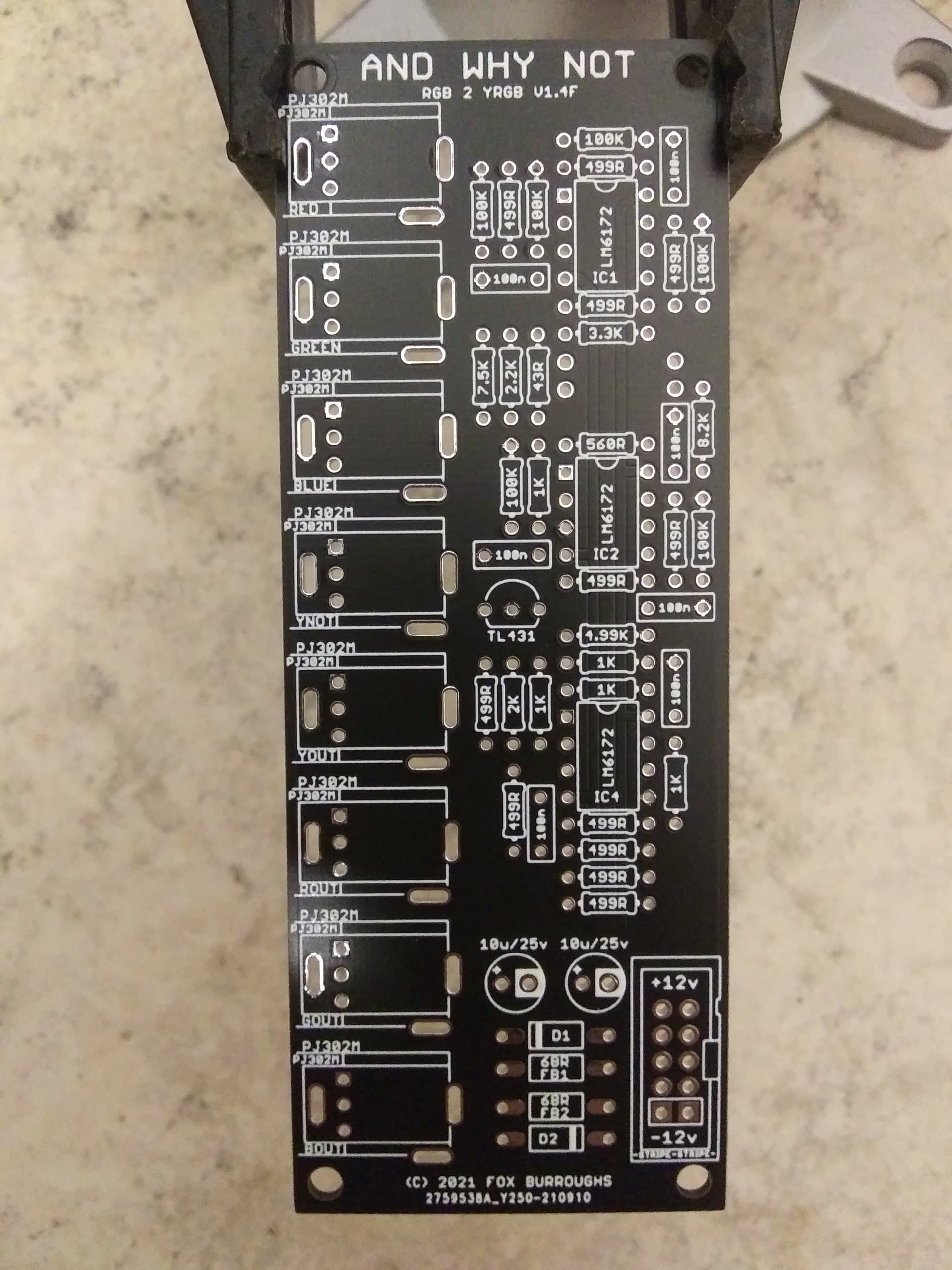
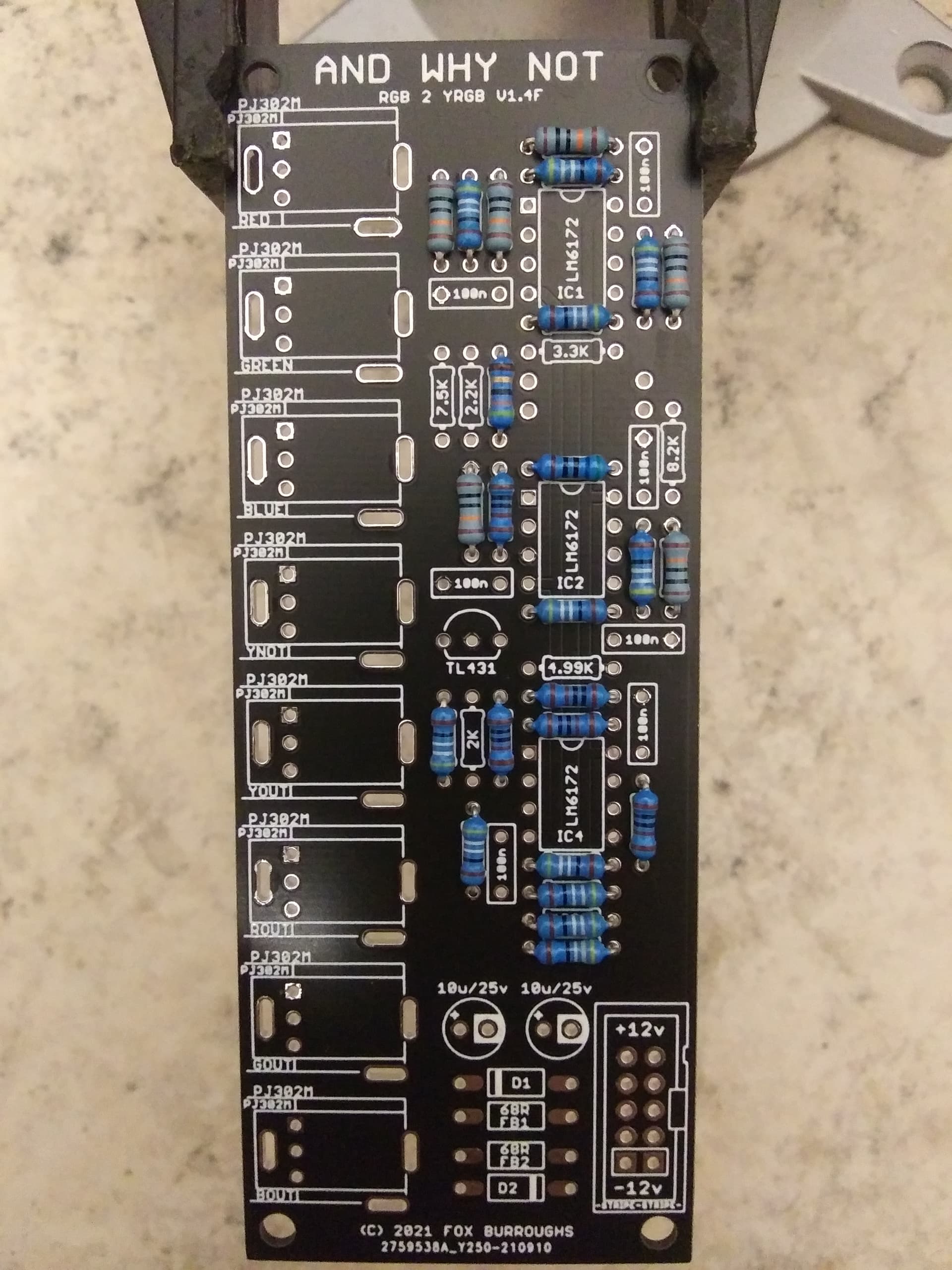
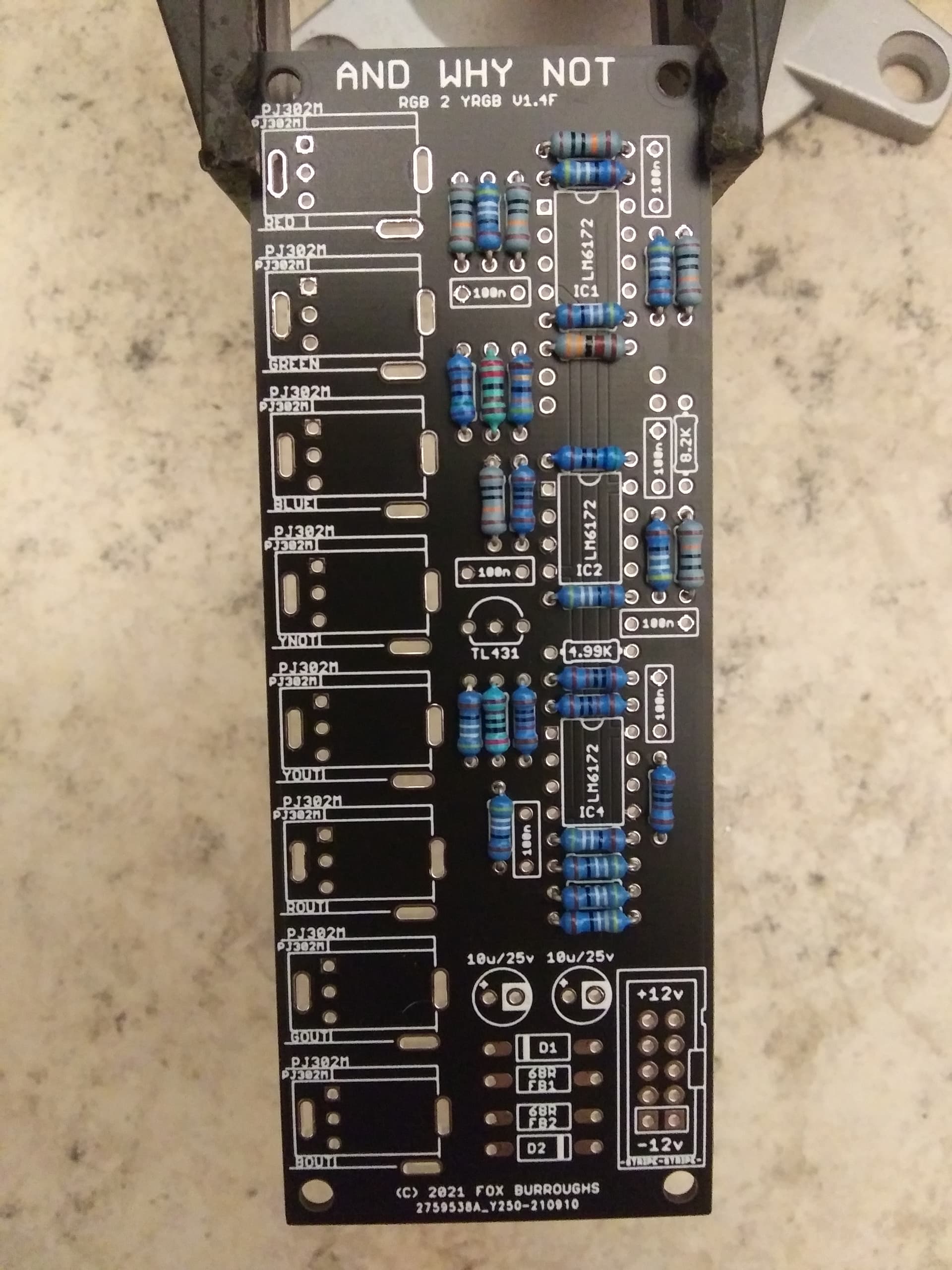
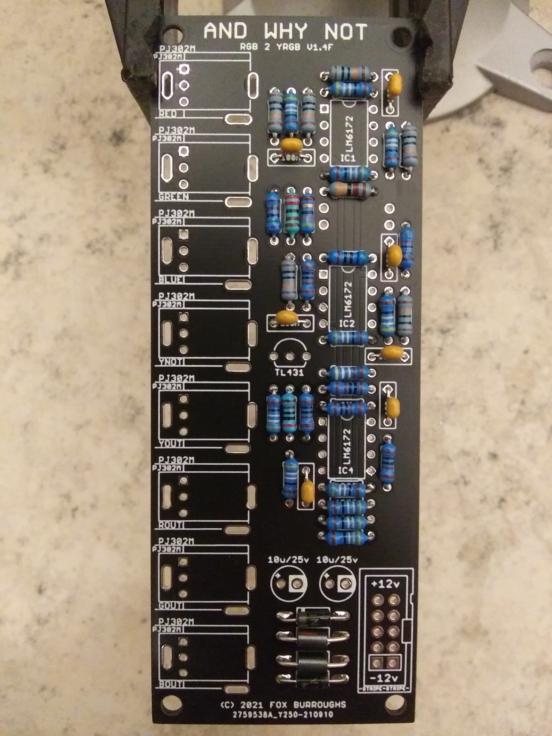
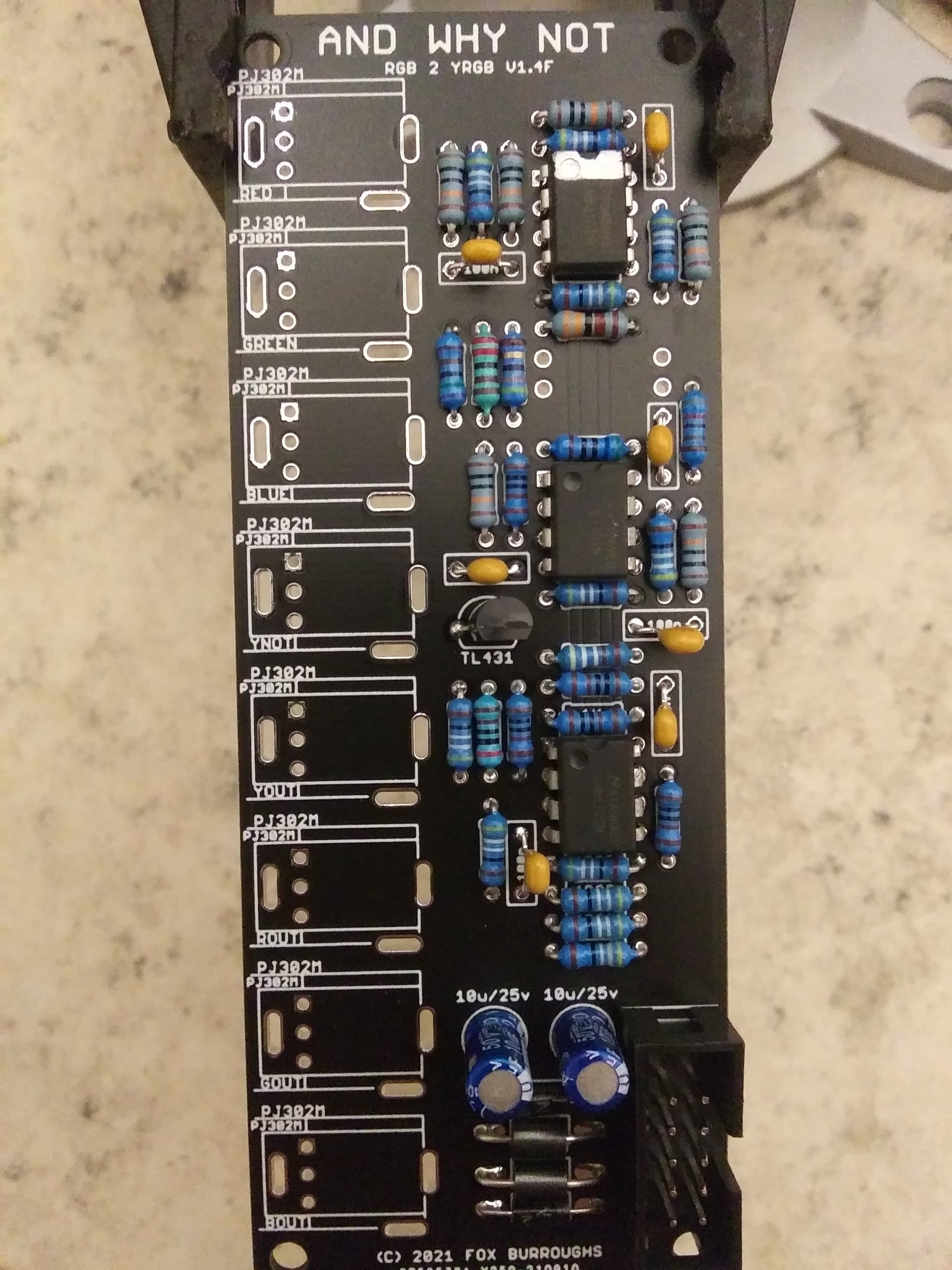
Using a PCB vice will improve your DIY experience immensely. Just another reminder: the resistor values are very important on this module. For highest accuracy, use only 1% metal film resistors.
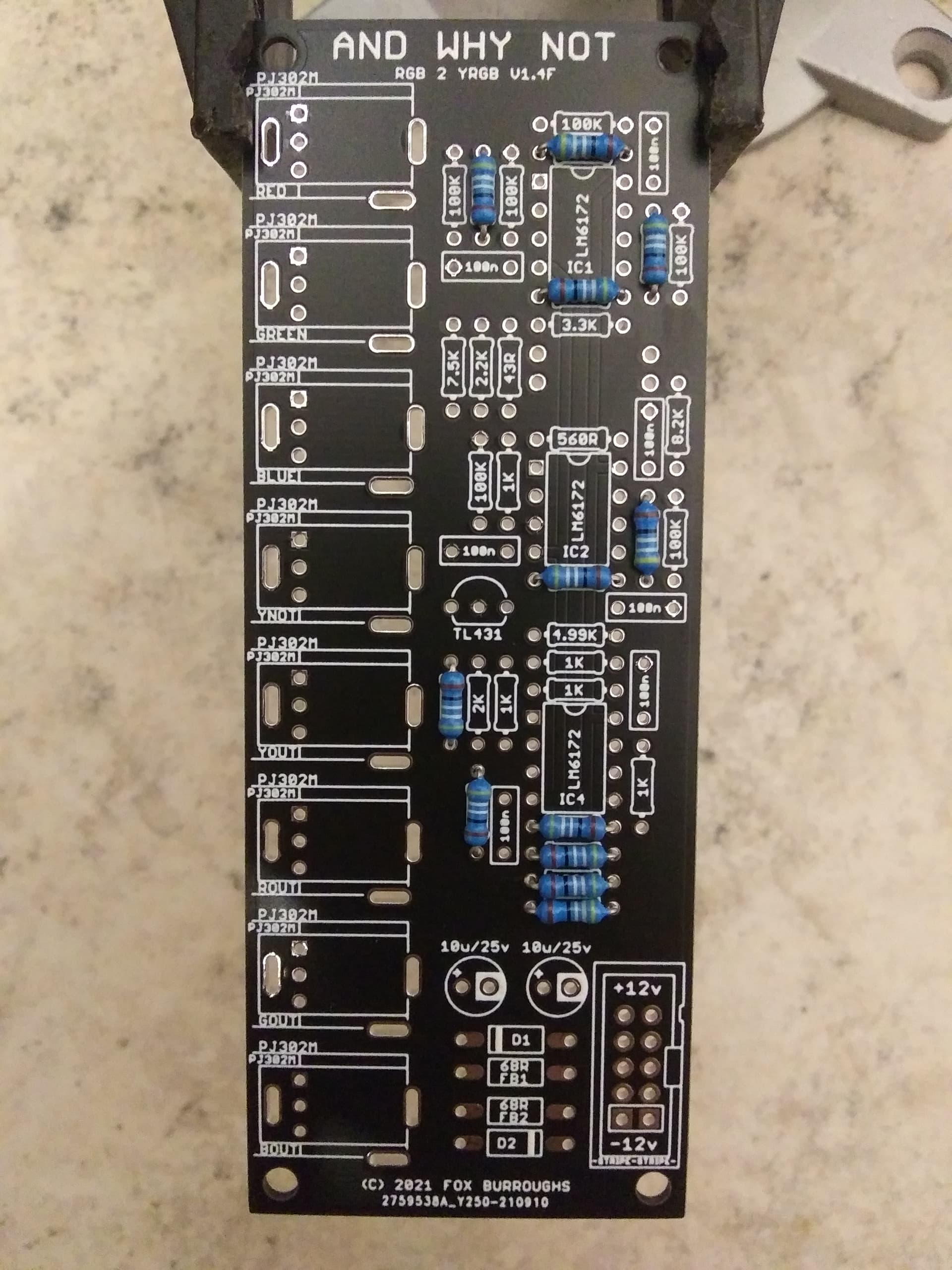
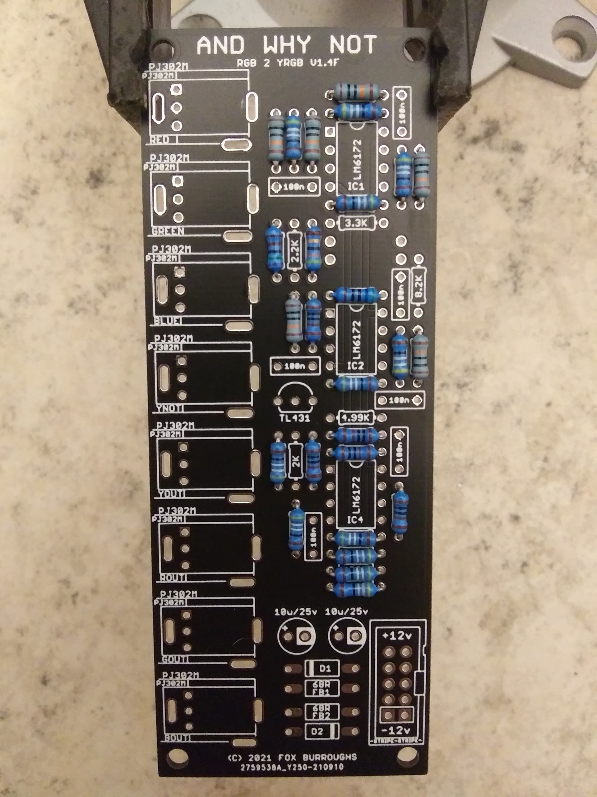
We will start by populating all of the shortest components. Place all twelve of the 499 ohm resistors.
I suggest soldering all of the resistors at once after you’ve finished populating them into the board.
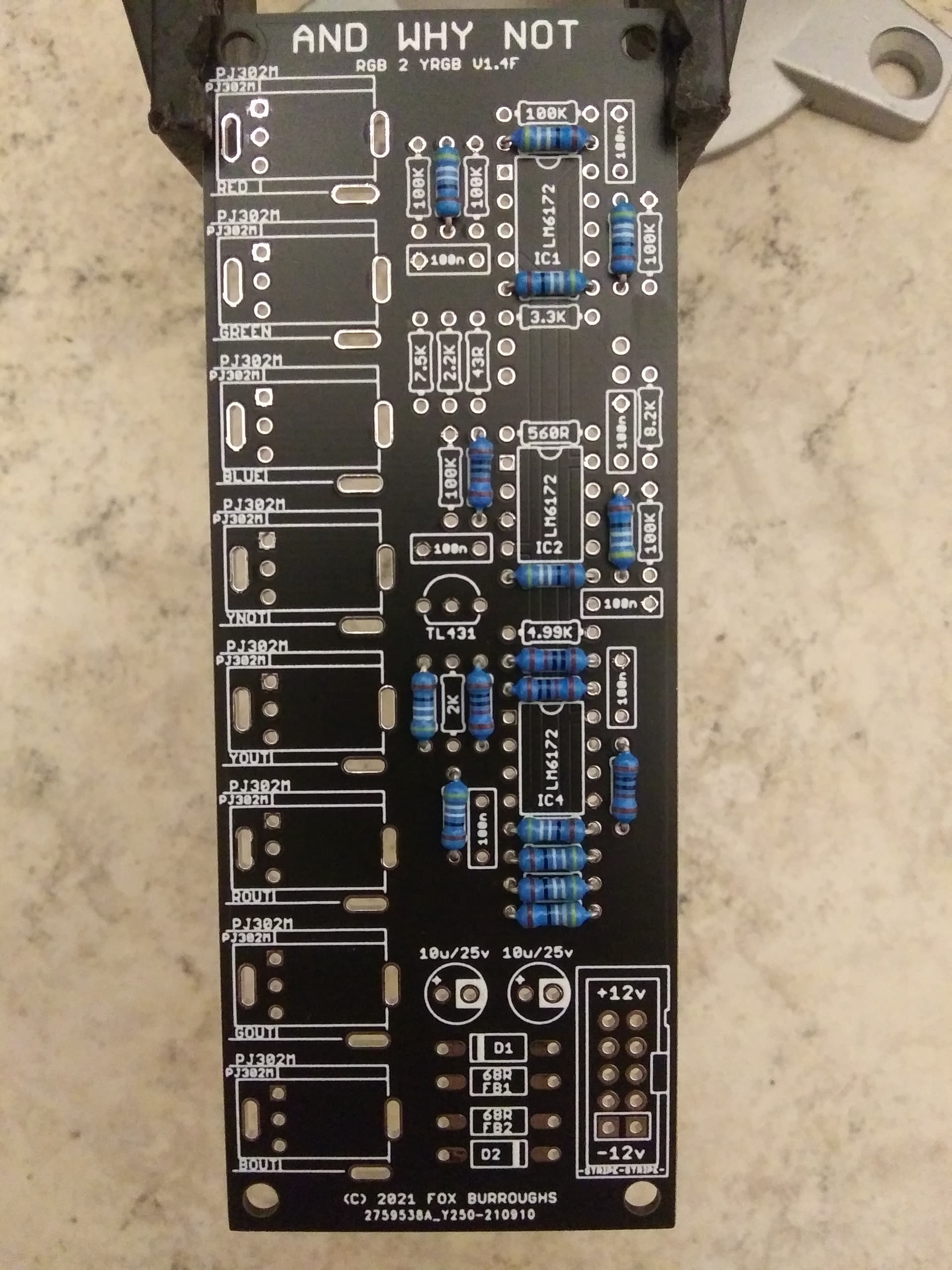
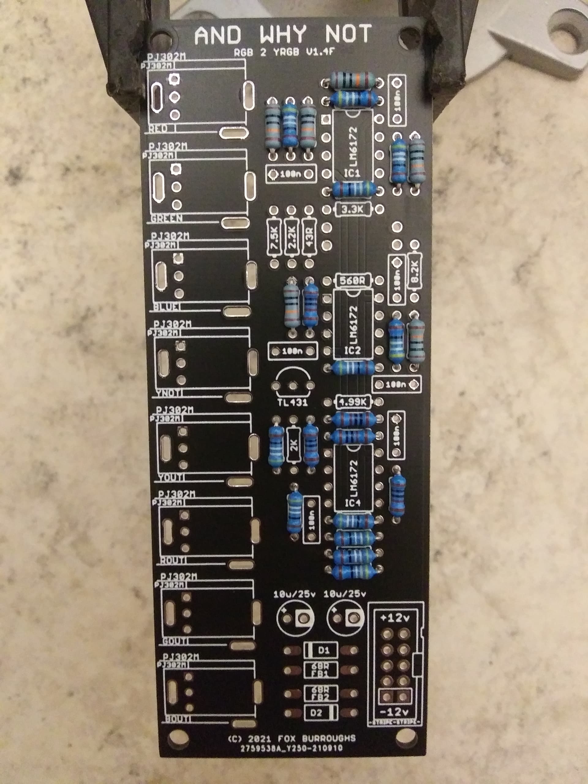
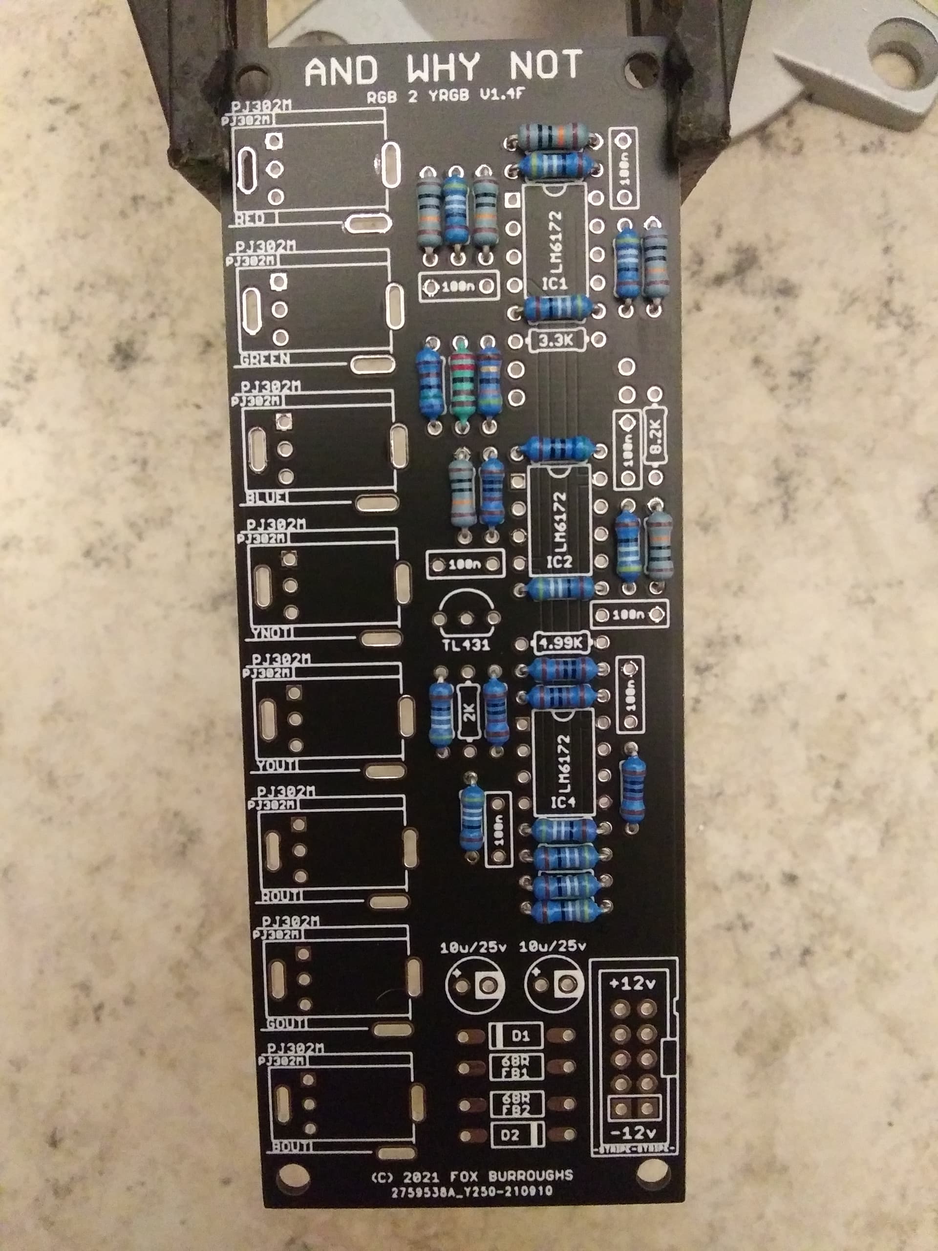
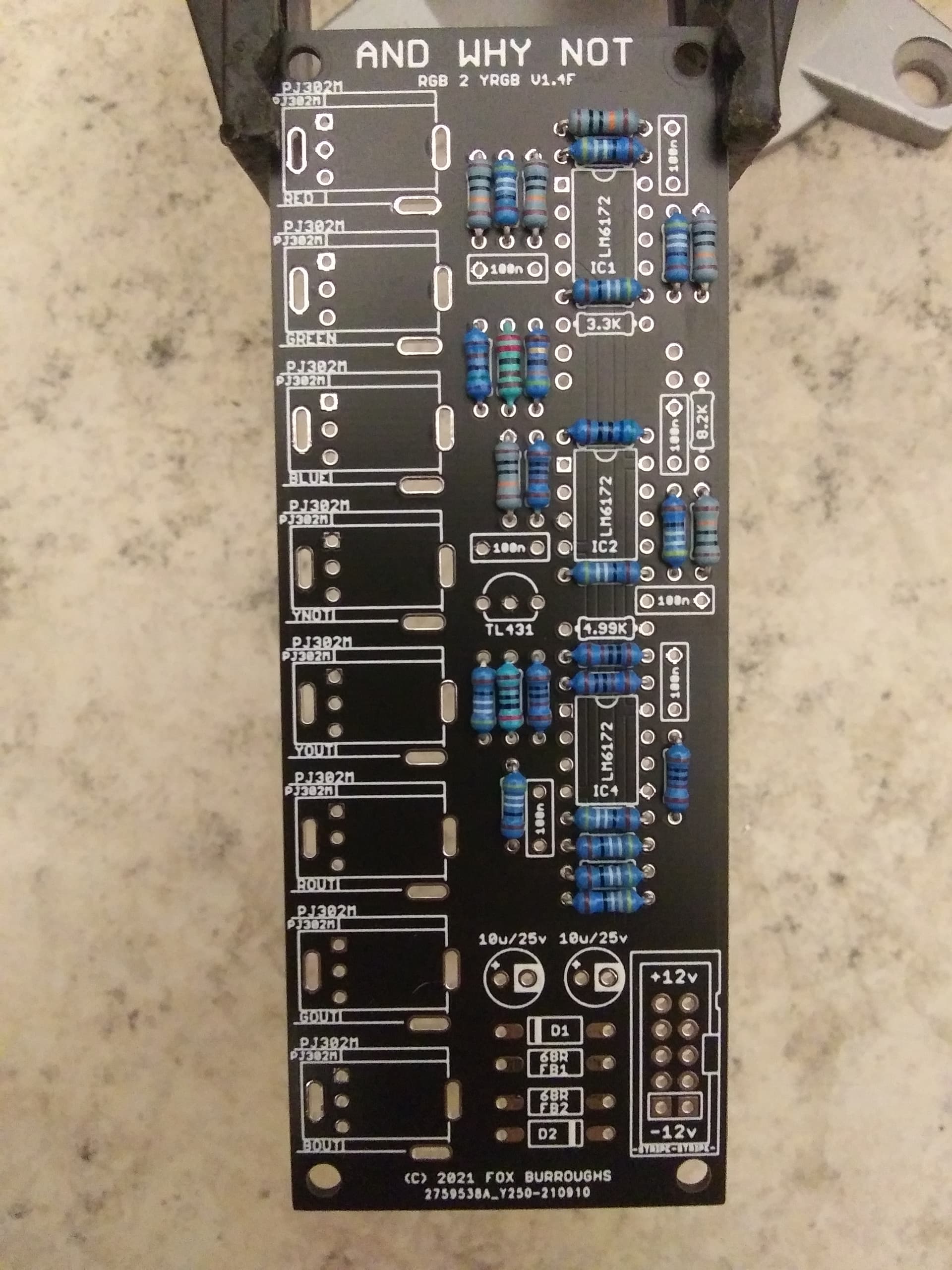
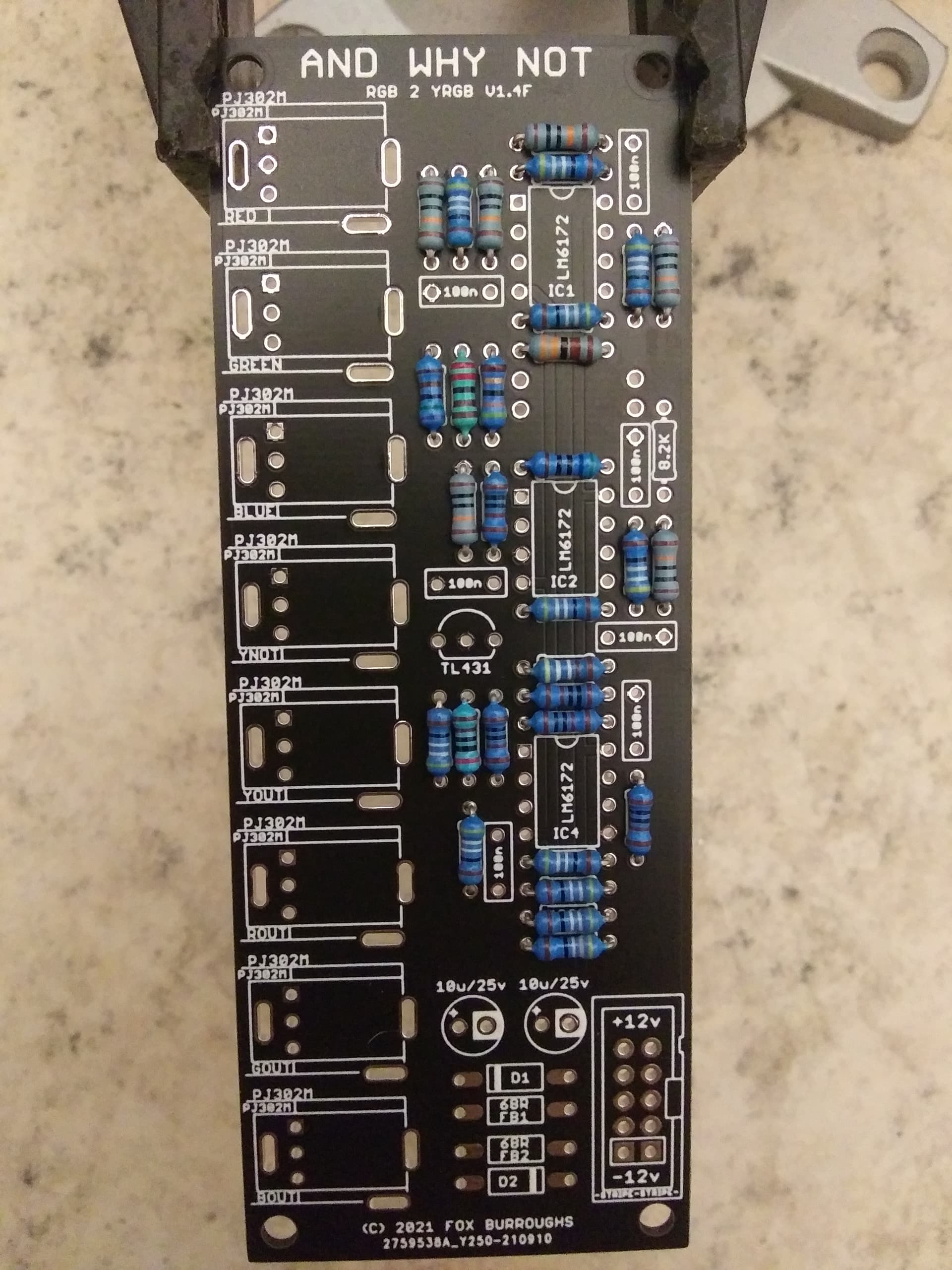
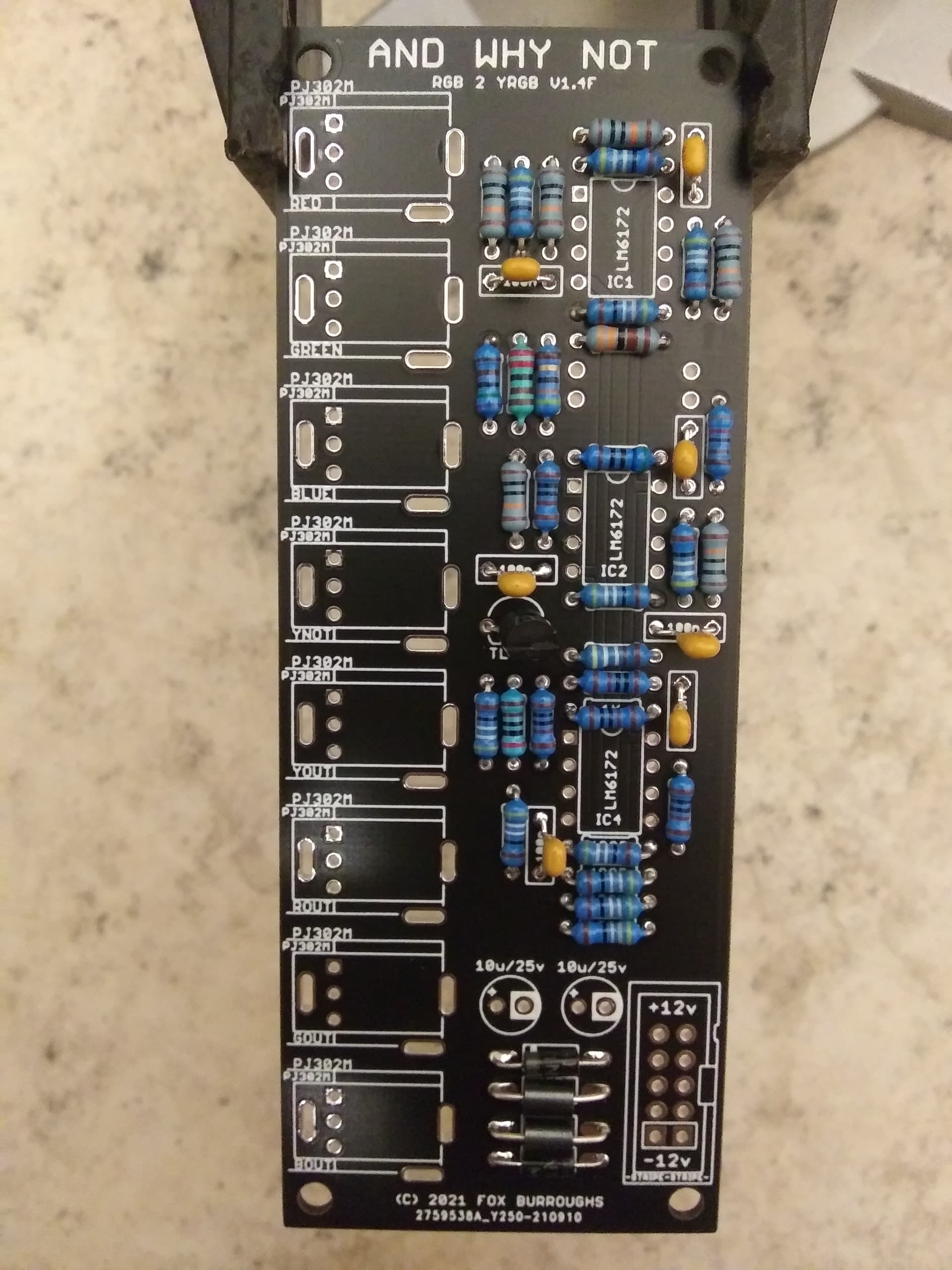
The remaining resistors are all different values but only have one of each. We’ll move through through these ones a little more quickly.
Populate a single 43R
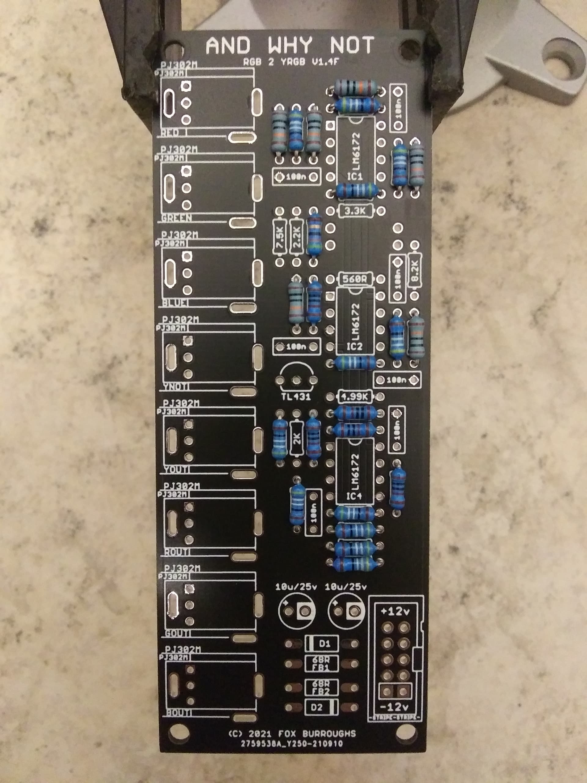
Step 5.
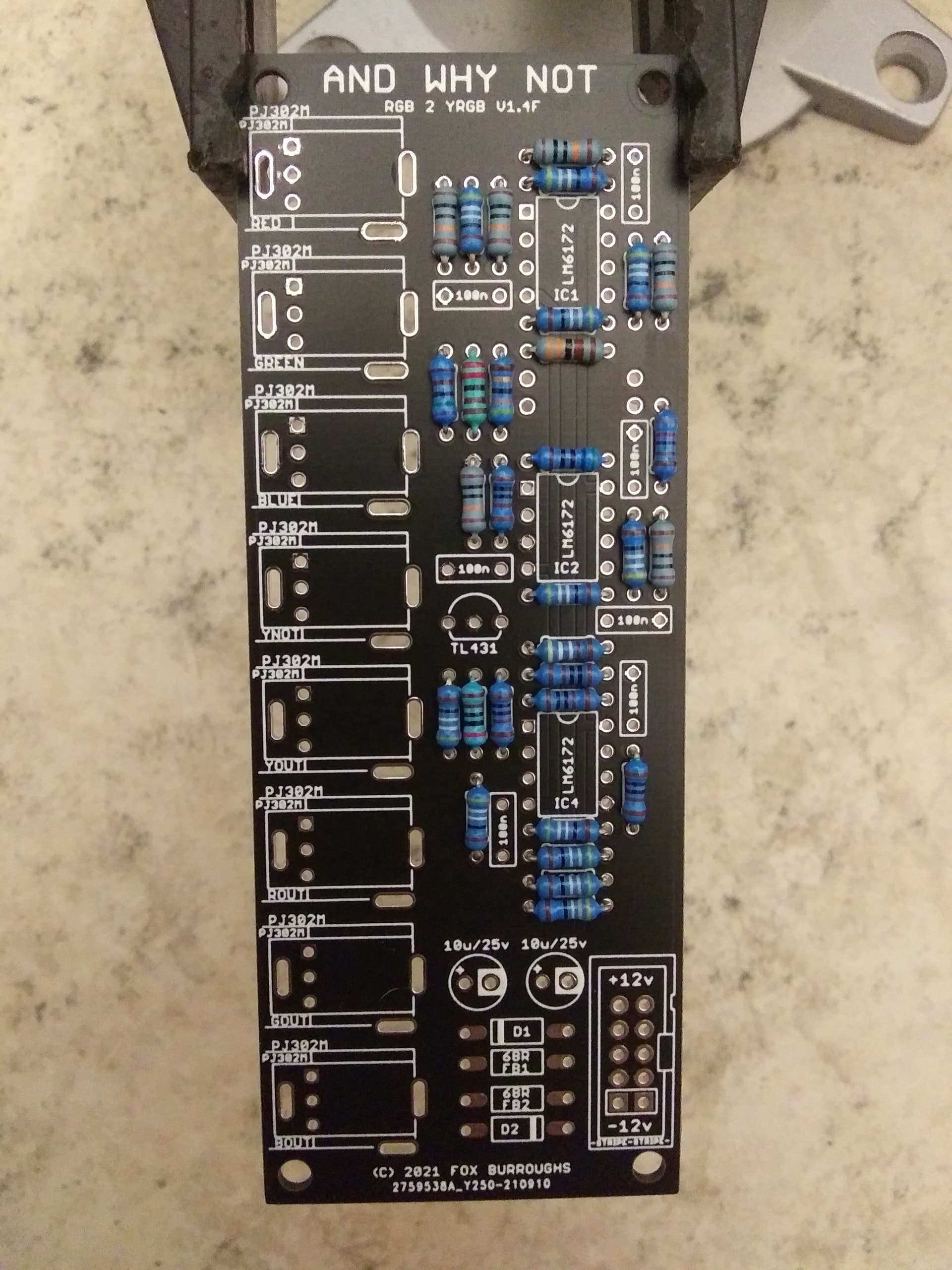
If like me you have waited to populate all of the resistors before soldering, you may do so now. Carefully flip your board over onto your work space and solder them in place. Clip all of the leads.
Step 6.
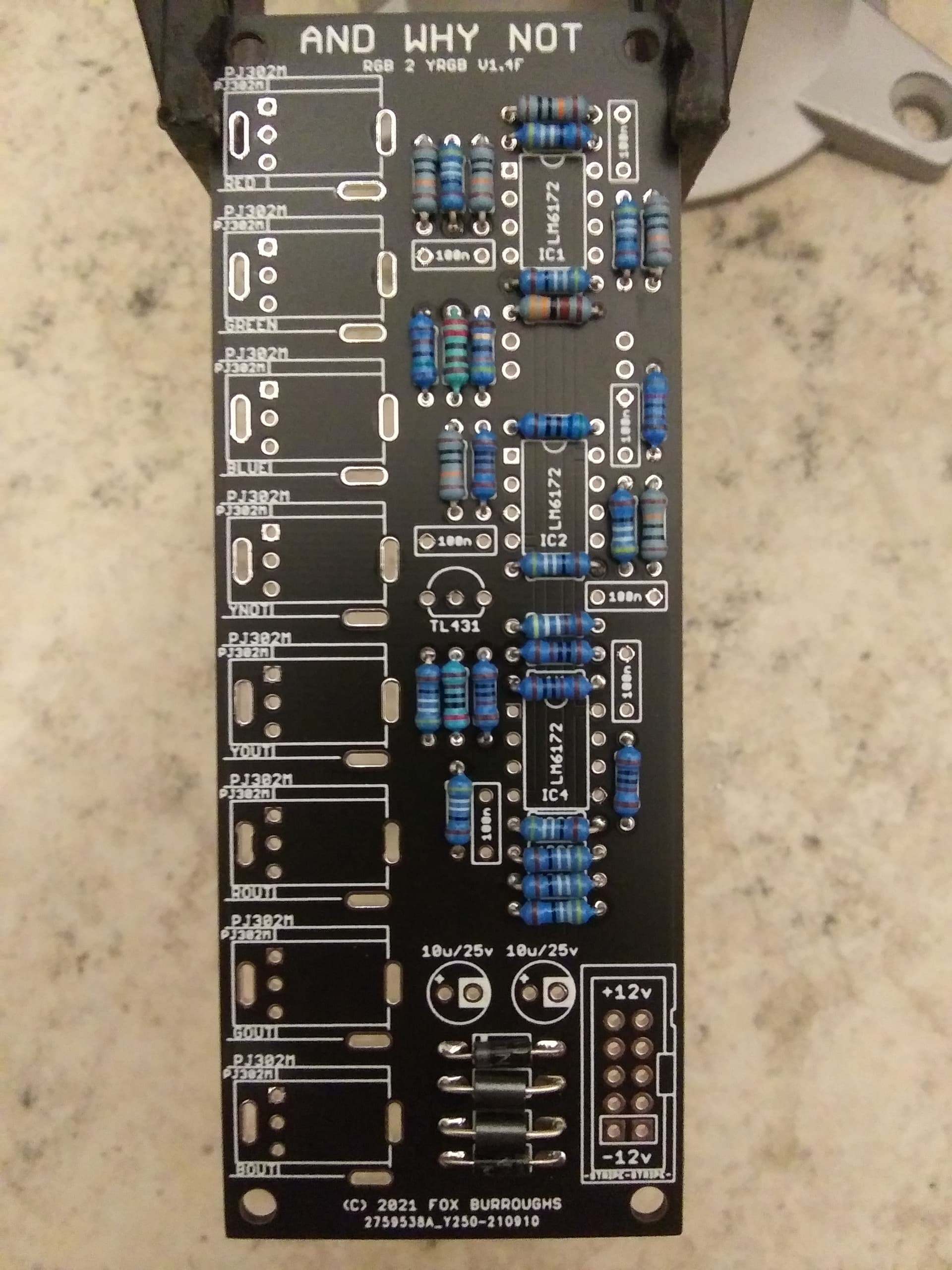
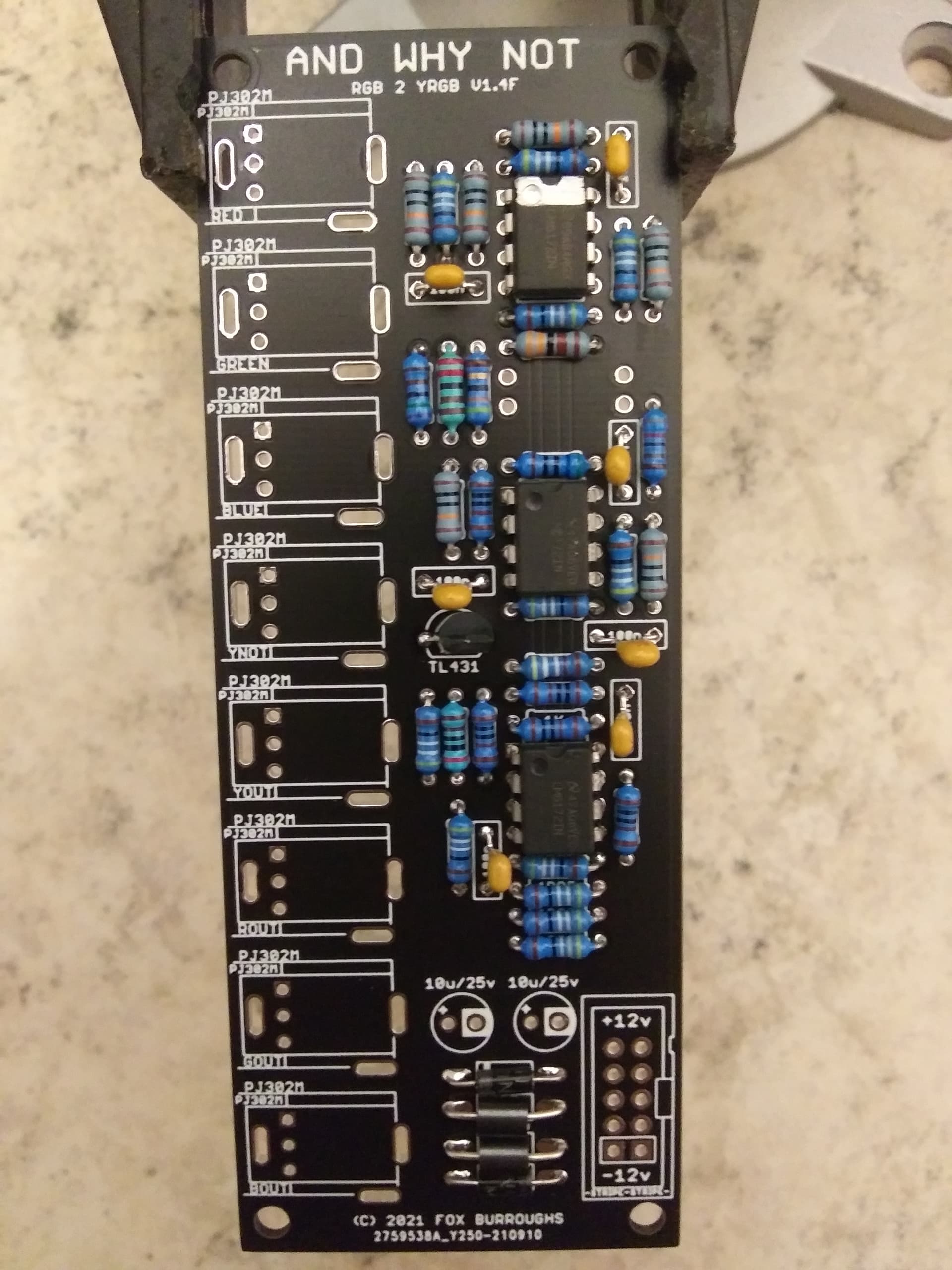
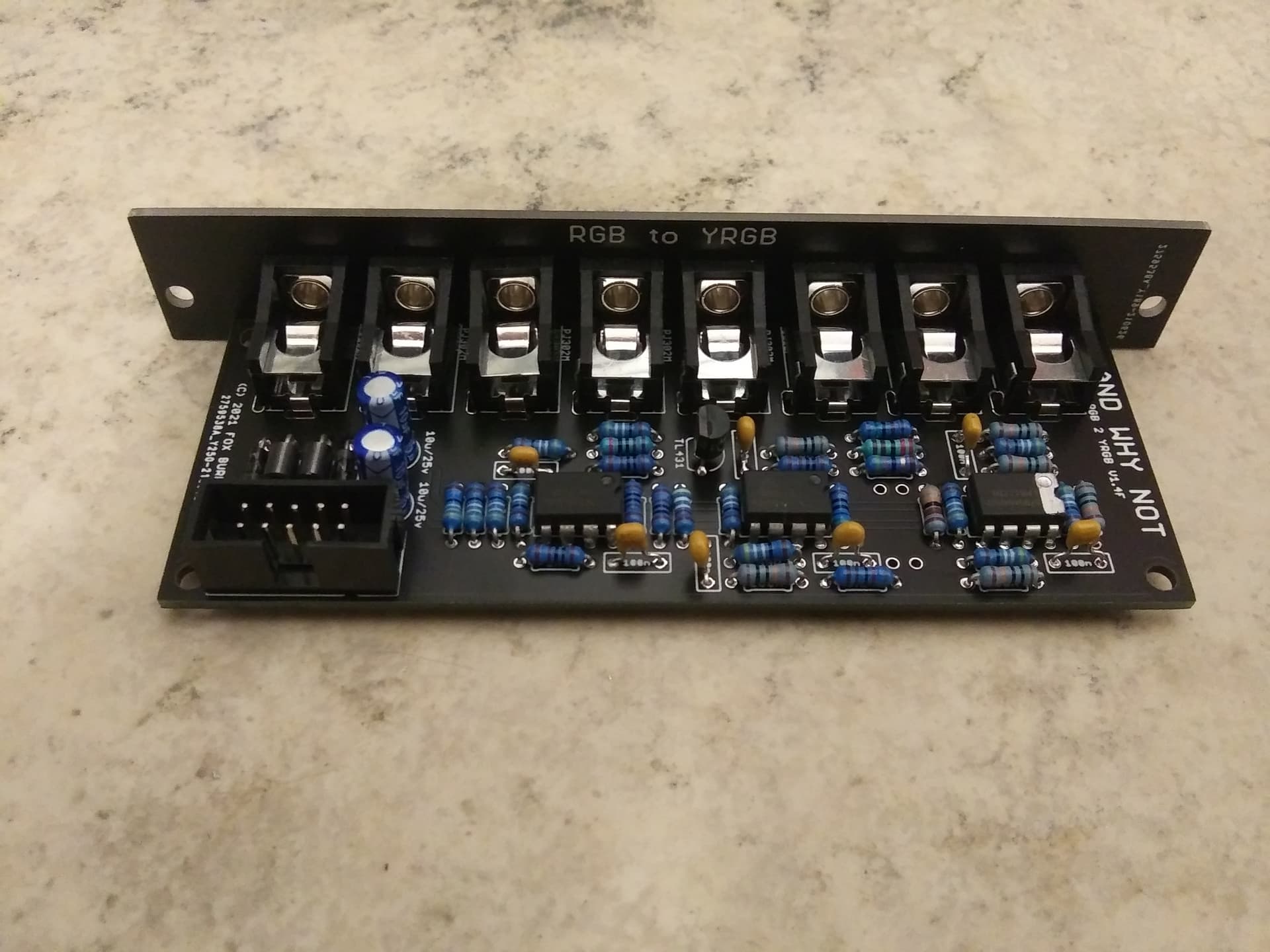
We’re moving on to the taller components now. Populate both ferrite beads and both diodes. Solder and clip leads. Take note that the diodes are polarized and the stripe on each diode must line up with the stripe on the silk screen.
Now you may populate all three of the LM6172 op amps. Be careful to place them in the correct direction. The silk screen shows a circle where pin one is to be placed. Pin may be identified on your chip by the adjacent dot in the plastic encapsulation.
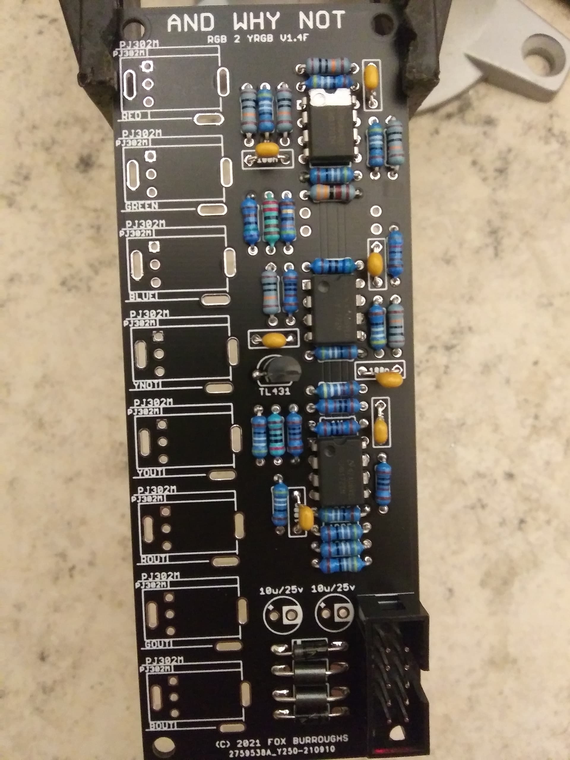
Populate the 10-pin power header. If you have selected a shrouded header box as I recommend, you will see a cutout on one side. Line this up with the silkscreen. (The cutout faces out)
Now populate both electrolytic capacitors. These parts are also polarized so line up the stripe on your caps with the pin that is circled. Solder and clip leads.
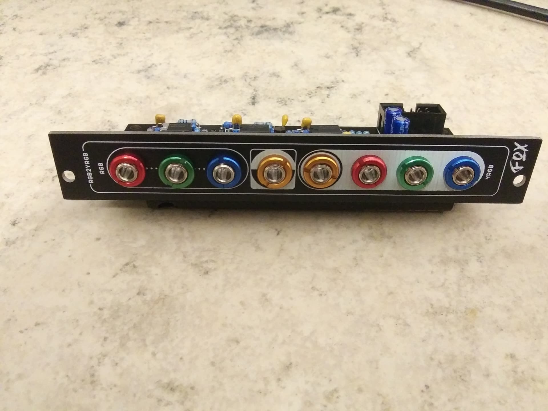
Finally you may populate all eight of the jacks. I suggest populating all of them and attaching the faceplate before soldering. This ensures that each one of them is lined up.
And to finish it off, I highly recommend you treat yourself and color code all of the ins and outs with some befaco banauts. Two of each red, green, blue and yellow.
Go ahead and test out your work.
You can also think of this as like the Luma output from the Visual Cortex Pre-Encoder Expander but you are able to use it at any point in your patch–not just after Cortex’s compositor stage. Anywhere you resolve an intentional RGB image or have 3 distinct signals where you want to use the perceived luminance/amplitude of a RGB image to feedback/influence another parameter of your patch, this is a direct way to do it + an inverted output. It doesn’t dead-end your patch to do feedback with RGB mixes anymore nor does it require a triple mult.
In the context of using it as the key input for compositing two separate images, you usually want to feed the Y output into a soft or hard keyer module and its output then goes into the VC control of a triple crossfader that fades between the RGB passthrough of LUMA and another RGB image. Consider these rough patch flows:
3x Cadet VCOs → SMX-3 for colorization → LUMA RGB Passthru-> SHUTTER Ch.A
Mix Cadet Ramp outs → SHUTTER Ch. B
LUMA Y → SHUTTER R Switch Input
SHUTTER Out → Encoder
3x Cadet VCOs → SMX-3 for colorization → LUMA RGB Passthru-> Marble Index Ch.A
Mix Cadet Ramp outs → Marble Index Ch. B
LUMA Y → Doorway Source → Marble Index Opacity CV (b/w Ch. A&B)
Marble Index Out → Encoder
The keying effect, instead of being like a screen wipe fed by a H or V ramp, will follow the brightness of the SMX-3’s output into LUMA. You get a much more intuitive luma key that more tightly or loosely fills in darker/lighter areas of the first RGB image with another RGB layer.
I’ve been putting it right before Cadet II and feeding it back into a BSO Crossfader that has the passthrough of LUMA 's RGB inputs and nothing into ch. B for black. Then into Cadet II encoder. Basically using it as a fine-tune VCA so negative space gets defined well.