I too love the groovy Expedition font, however I prefer the ‘pro’ look of the Gen3 typeface. What is the new font?
1 Like
Me 3! ![]()
1 Like
The typeface is Goldplay Semi Bold. Typeface is a big choice for me and I’ve tried to refine our choice over time. This typeface really works for me – it is legible and polished as a technical / academic font, anachronistically playful but not over the top, and design wise soft and geometric to represent our brand itself. It is, proportionately, the most circular font we’ve used to date – I feel like it really harmonizes well with all the other round elements on the panel and print.
There’s a free version of one of the line weights available for download here:
2 Likes
I guess, in my ideal world, these would be user-selectable as either +/-1v or 0-1v.
Not sure if I already said this or not, but… Agreed!
My one kvetch on typography would be that knob labels feel uncomfortably close to the range markings:
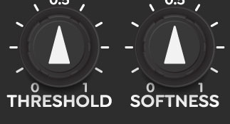
An extra millimeter or two would go a long way there.
Assuming SMX3 has normalled 1V reference to its inputs when they’re unplugged, you could just plug the bipolar outputs from DWO into one channel of SMX3, attenuate it by half (+/-0.5V swing) and then add 0.5V with another unused pot in the matrix for 0-1V swing. For quadrature modulations, it’s much more important that these come out natively as bipolar signals. It’s only at the encoder that signals are clipped 0-1V so a ton of processing can be done thru zero in between before it hits that. Being able to access these directly for vector applications is huge, too. Doesn’t seem like there’s much room for additional switches on DWO as well.
4 Likes
Think of it like the DWO3 provides the positional element:
- Vector (Ramp Out)
- Mirrored Vector (Triangle Out)
- Phase Angle (Sin/Cos Out)
- Clock (Square Out)
And DSG3 provides the textural element:
- Parabolic Shaping (creating Circles)
- Exponential Shaping (creating Stars)
- Rectification (pattern divisions and multiples, Triangle)
So the Parabolic/Expo shapers on DSG3 are your textured sine outputs. It’s just that you are splitting quadrants across XY axes before the shaping occurs (so that you can rotate and split and fold and rectify the linear Cartesian Vector before the parabolic shaping occurs – where it is most powerful, inside the patch.)
The bipolar sines will feel pretty natural, even as default modulation/Texture sources. Just think of them as “Blank Circle Blank Circle” or “Circle Blank Circle Blank” waveforms when used directly as textures. If you want “Circle Circle Circle Circle” that can be done with the rectifiers on the DSG3.
So a Gen3 synthesis workflow goes like this.
- STEP1 Generate a positioning vector (HV ramps, sin/cos, etc)
- STEP2 Modify/processing/shape the positional vectors
- STEP3 Synthesize a color texture (RGB out)
And some notes:
- DWO3 is the most basic STEP #1 module. It’s optional because the other modules have default HV ramps internally.
- DSG3 is the most basic STEP #2 module. Ramp crunching waveshapers for making 2D patterns. It’s optional because you can always use DWO3
- STEP3 is you and your cables! It’s in how you patch the sources from DWO3 and DSG3 to an RGB input somewhere.
4 Likes
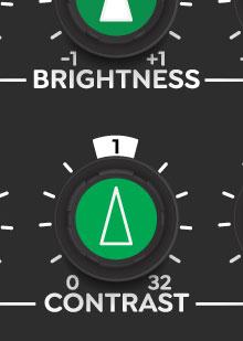
They’re a little close I agree. If this were art for a poster I’d think about it a little differently, but in this case that’s an intentional decision for a few reasons:
- The type and all components are laid out on a 100 x 125 mil alignment grid, it’s been part of our standard since the beginning. That ensures that when it neighbors other LZX modules, headings and controls will all line up. This typeface is a point size larger than our old one in Expedition, but the knob sizes are the same – so that’s why it’s a little cramped
- Especially with the black backgrounds, it’s very easy to lose which label belongs to which knob if the spacing is at all ambiguous. You have to end up doing mental gymnastics like “well it’s closer than this other label is” or “all the labels appear to be under the controls, so it must be this”
Admittedly I love it when this happens – breaking a design rule, but it does so in sacrifice to maintaining some consistent usability logic. It throws you off at first, but then by doing so only strengthens the underlying ruleset. And it allows a history (and a conversation) to develop over time.
5 Likes
interesting font here (apparently debunked - does not improve recall):
https://sansforgetica.rmit.edu.au/
Looks interesting, though.
2 Likes
I was/am curious how that font would look like on the faceplate of a futuristic LZX video synth module.
1 Like
That’s a really cool font! Maybe we’ll play with it in the layout for the patch diagram book I want to do.
2 Likes
I’m not sure if I saw this specified already but in the instance of TBC2 as the parent sync, will ESG automatically update its sync format or would you have to adjust the dip switches?
1 Like
It will auto detect the format. The DIP switch setting only matters if it’s an independent operator.
There’s one exception, and that is that the YPbPr vs RGsB colorspace setting is defined on the DIP switch. So that setting is always local to the module, since we can’t decode a colorspace mode from the sync signal itself.
3 Likes
We had fun bringing FKG3 to life this week! (Non production faceplate / knobs). I’m excited to record some HD tests with this keyer, TBC2 and Chromagnon next to share with you all.
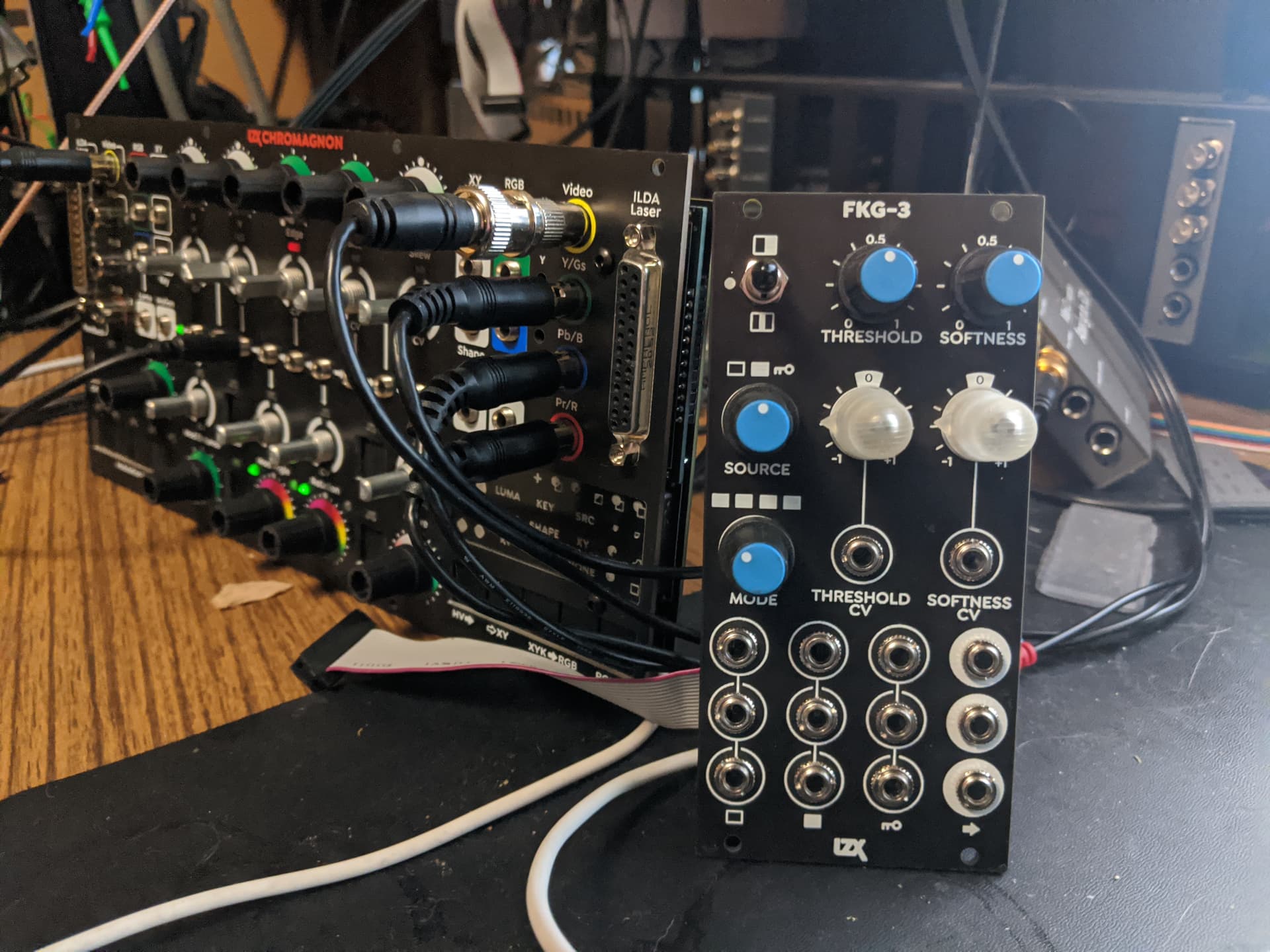
19 Likes
I, for one, am very excited.
2 Likes
Two modules are now available for pre-order!
10 Likes
Is RMX-3 Matrix Router functionally an inverse SMX-3 Matrix Mixer? As someone with zero real knowledge of what the underlying circuitry for these things looks like, could the functionality of these two modules not be combined somehow, given how similar their interfaces are? Again, I don’t know shit and am pretty much just looking at shadows, I just think the interface/functionality seems unusually similar.
I love the functional design and aesthetic of these modules. And basically everything about them, the more I look and think about them.
2 Likes
Yes, they are inversions of each other – the Matrix Mixer expands your system’s total number of inputs, whereas the Matrix Router expands your system’s total number of outputs. If we put both functions on the same module then you can’t, as the user of this modular toolkit, adjust that IO ratio yourself.
Some systems won’t need the router. Some won’t need the matrix. Some may want multiples.
If you want lots of color mixing control of individual components, or to mix RGB sources with abstract RGB or luma sources, you want the Matrix Mixer.
If you want lots of modulation routing, animation rigging, flat color/palette programming, parallel motion paths, complex VCO control schemes, etc. you want the Matrix Router.
We’ve been considering some other approaches to the router. But as the concept is at the moment, they are intentionally similar so as to be symmetrical building blocks – like a left bookend and a right bookend.
7 Likes
Lars, just making sure I got it—are all Gen3 panels manufactured with FR4 laminates? thanks
Lars, just making sure I got it—are all Gen3 panels manufactured with FR4 laminates? thanks
Correct. Production modules will have black FR4 panels with UV color overprint. We print a translucent layer of color over the PCB silkscreen in house with our UV LED printer. It looks great, is durable, and ensures we can go from a PCB order to a shipped module within a couple weeks lead time. The black color + white silk coming from PCB fab is a design choice motivated by the color overprinting method, which would not work the same way on a white panel.
I think the FR4 panels look great. But would like to offer anodized or powder coated aluminum panels with 4-color silkscreen, or Metalphoto panels in the future,. Those would be offered as OEM replacement parts and not a base/assembled option.
I’m also happy to open source the dimensional drawings of the panels for anyone wanting to make their own replacements for personal use.
In general we want to offer more options with this series, and more customization, and keep this series as our core offering for many, many years – meaning an accessible OEM/DIY catalog of replacement/alternate parts, knobs, subassembly options, etc.
17 Likes
I am so happy to see the new shape transformation tool finally seeing the light of day. 
I have always wondered what the maximum level might be for modules like this to work with still images loaded from an Andor1 for example. I know Memory Palace is the ultimate tool for deforming those complex images and videos, yet I have never seen a demo to know how far I could go with a shape transformation tool. Could it be “just” ramp like shapes or grids or what could the recipe be with them? I only saw Shapechanger in the 3 Patches series being used for processing external video, yet it only added some distortion/artefacts on the input. Hope you could get me even more inspired!
1 Like