ok so I checked the Sync Gen and it seems ok. I don’t see continuity between the output of R20 and any of the pins of the syncplug. BUT if I look at R27 on the Cadet Ramps I see a signal (with same amplitude on both extremities of R27 which seems strange to me) identical to the Vsync jack out of the SyncGen: it has think spikes at same frequency only at R27 they are 5V of amplitude while on the output of SyncGen they are at 1V. Estimated spacing 15 msec. Switching NTSC to PAL in the SyncGen doesn’t seem to change anything, which is also strange.
I tried changing the opamp and it does the same.
Strange thing is: after pluging and repluggin sometimes I see in the V output of the Ramps some little ramps (not long but quick, check the pictures) sometimes nothing. I think my SyncGen could be fine. Don’t know what could be wrong then. I have a dual scope so in the picture you see the sync signal from the SyncGen (below) and the V Ramps (above). Only difference the time scale. Maybe the cap is too fast in releasing the ramp? I dont know what I’m talking about but that’s the only difference in both circuits H and V.


The voltage range going into U7 on the ramps board should be 0-1v and the output should be 0-5v. The op amp may be good then.
I wonder if the connection between R20 (CADET I) and U7 (CADET IV) is broken. That could point to either 14-pin connector or even the 14-pin cable itself.
If the input of an inverter (U7) is left floating, it will probably self oscillate at the output so if R20 does not connect to U7, then the inherent capacitance of the traces and cabling would determine a specific frequency of self oscillation (for example 15mSec).
I think you should investigate here:
I don’t see continuity between the output of R20 and any of the pins of the syncplug.
EDIT: Oops, I said 14-pin connectors and ribbon cable. But R20 should go to the 16-pin cable.
Hey Fox thanks!!! My problem is I don’t know to which pin it should be connected to. I don’t see it even of the same board of the SyncGen. I just see the same frequency in the jack out and the sync in to the Ramps so I would think it can’t be self oscillation. But then again I don’t know much. Maybe there is a sort of resistance that is non 0 between r20 and the pin of the sync plug…
I edited my post above to say that I meant 16-pin ribbon cable and not 14-pin ribbon cable.
R20 must connect to the GATE pin on your 16-pin power ribbon.

Jeez, I just put the schematics side-by-side again and Ramps doesn’t use the signal from R20. It DOES use the signal from pin 9 on the 14-pin ribbon cable. Tracing that back, the signal goes to U7 on CADET I which in turn gets the v/hsync signals directly out of the Atmega.
Backing up, I know you replaced Q2 on your ramps board, but didn’t say if you had looked at Q1. Both Q1 and Q2 are supposed to be 2n3906. Just to be clear.
Thanks so much Fox I think I found it there was a broken trace somehow. Now it all works almost fine. I just have not the best looking ramp in
the H triangle. Here is the picture. Moving the trimpot it feels like I just need more resistance to make that central bump disappear. What do you guys suggest can I add a bigger resistor in place of R4? Which value would you say? Like 10k?
Thanks so much really for the help!!! I’m almost there!!! :))))
No, R4 won’t fix it. R4 is for the V-sync portion anyhow…uh, correct me if I’m wrong. Maybe you meant R2.
This looks like a symmetry issue with the Triangle shaper portion. Can you verify resistor values, solder continuity and diode polarity of this portion:
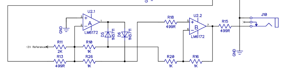
I suspect R10 and R26 must be very close in value to achieve that shape we need. Of course, R18 and R20 are just as important here. My reasoning is that one side if the triangle is being attenuated at a different amplitude than the other side; each side being technically the same triangle, but inverted and non-inverted versions summed together through the diodes.
HI Fox, thanks a lot for the wisdom. I checked the color codes and they are ok, diodes and continuity. All resistors are 1%. I can also run a value check tomorrow. Anyway whenever I turn the trimpot I see also the other two curves not reaching their optimal point. That’s why I thought the problem was that I need more resistor in my trimpot. In my Horizontal trimpot I am using the max position and I luckily to get perfectly where I want. So maybe it’s just my whole values don’t add up as expected and need to tweak a resistor somehow before or after the trimpot.
The trimpot/R2 combo can only attenuate the signal since both sides of it are buffers. R2 sets the low limit of possible attenuation while the high end is 1:1(no attenuation). This isn’t a gain stage, but it sounds like you want gain.
Theres also the possibility that the capacitor (C29) is not charging to a high enough voltage within the time of one Hsync. I’m not sure which resistor fits into the RC equation, but even the value of C29 would affect the rate too. But It would probably have to be off by more than 10% to see a difference.
I am not certain enough of this part to offer any suggestions. Maybe someone else will chime in with a better solution.
I looked at your color codes too and everything seems to be right, at least visually.
thanks in the meantime I’ll check the values of the resistors to see if there is one off. solved most of my issues anyway  This is a great community <3 Maybe I’ll wait a week and in case I’ll ask again on Facebook.
The circuit section that Fox posted is a Full Wave Rectifier - it works by taking a bipolar signal and inverting half of it. By doing so it gives the fade from 1V to 0V back to 1V across/down the screen.
The trimpot adjusts the amplitude of the ramp output from the oscillator core U12.2. You want that waveform to be a 0V to 1V ramp from one edge of the screen to the other, so it can be buffered to J8 via U12.3. The rectifier circuit doubles that input signal to 0V~2V (R13:R26 ratio is 2:1) and adds half of the -2V reference as an offset (R11:R10 ratio is 1:2). So the -IN to U2.1 is a ramp from -1V to +1V. The rectifier inverts the negative portion of that wave, resulting in a 1V to 0V to 1V waveform. Got all that? So, if the trimpot is adjusted then the waveform has more or less voltage above the (effective) 0.5V threshold around which it is mirrored to form the V shape. So yes, changing the trimpot should adjust the symmetry of the V shape. If you’re at the extremes of the trimmer than you could reduce R2 to allow you to reduce the amplitude of the wave, but to increase the amplitude it’s not so easy, since the non-inverting op-amp feedback resistors of U12.2 U12.3 are currently zero, restricting you to unity gain (see https://www.electronics-tutorials.ws/opamp/opamp_3.html for more information about that). But reducing R44 slightly should result in higher current flow into C29, resulting in a faster charge and therefore a higher potential (i.e. voltage) before the reset happens.
In response to some of Fox’s points then:
- R10 and R26 are important, but only in relation to R11 and R13 as they set the relative thresholds for the mixing of the (scaled) -2V reference and the main ramp signal and therefore control the rectification point.
- R10, R26, R20 and R16 must all match, or else the ‘angles’ of portions of the rectified waveform get skewed.
- R18 is actually not important at all, and could probably be replaced by a wire link!
Jester, check the voltage of the -2V reference, and make sure it’s correct. Replacing R11 with a 2.5K trimpot (wired as a rheostat) would allow you to adjust the rectification point independent of the amplitude of the other outputs, but that really shouldn’t be necessary if all of the resistors mentioned above are correct.
Sorry for the complicated description - I probably need to draw a diagram of the waves at various points! The take-away here is simple, though: Lars is smart
@VisibleSignals Excellent description and suggestions. I completely overlooked the -2v reference because the Vsync triangle looks good, but adjusting R11 will change the “fold point” of the Hramp and could make the H triangle symmetrical again without affecting the V-outputs!
I see now how the H-ADJ trimpot and R2 could change the shape of the H triangle too.
@jestern, As for the vertical line down the center of your two ramps, this is a common side effect of rectifiers and should not be visible on your tv. If you zoom in far enough on the V ramp, you’ll likely see it there too.
Thanks guys I understood more or less I’ll check the values of R10, R26, R20 and R16 first then in case replace R11. I’ll ask if I have doubts !!! Almost there I feel.
Ok guys I solved it I have now a working Ramps. There is still a little bump in the middle of the triangular wave but it seems acceptable in the image. I think my old scope was driving me insane and I could not see what I was looking for possibly it was working when I left few weeks ago. Anyway now it’s solved. The problem now is the input from my Extron but I’ll ask it in another thread thanks so much <3 <3 <3
Great news!
This sentence is padding to get my post length to 20 characters.