Animating and modulating colours

The cost-per-HP is pretty flat in how we’ve designed/optimized Gen3 series. In other words, a 24HP SMX3 that included a 3X3 multiplier CV input matrix (in addition to the knobs and jacks) is going to work out to a similar cost as 2x 12HP SMX3s already do. Audio circuit design can jump past a lot of the infrastructure cost (low noise integrated power, individual IO buffers for every single jack, etc) that we need to employ to ensure performance consistency.

Also, just from a personal perspective, I feel like “expanders” are kind of redundant and bad design, in a system that is already intended to be modular – where all modules are by definition, expanders to each other. The exception is when the expander lowers the cost or solves some production related issue that serves the user better or amplifies the value of their investment. So if we could make a multiplier expander to SMX3 that only costs $50, then that would be well worth it! But if it costs the same as another SMX3, then it’s better design to just make the expanded function a unique thing.

So the 12HP option is about making a $399 matrix possible, so that you can complete the picture by combining that function with other modules like SMX3+FKG3 (matrix crossfader/keyer) or SMX3+ESG3 (make your own colorspace style output amp) or SMX3+DSG3 (minimal color graphics synthesizer). It’s in these kinds of pairs that the Gen3 modules really start to take on specific workflow/instrumentation identities.

There are of course, bigger than 12HP functions that would need to be behind a single module to exist efficiently – a 24HP “Matrix Multiplier” is a good example of that.

3 Likes

To paraphrase, it makes better sense from your design and business perspectives to build bigger modules rather than expander options. Additionally, cost per HP is constant. By that I assume you mean all costs… development, parts and labor, and wholesale/retail.

Fair enough, I was thinking of configuration flexibility. My specific example was of a simple, dumb CV expander rather than a full blown matrix multiplier. I wondered if it would be cheaper to build a CV expander by retrofitting the existing module, rather than designing a new module with a new interface board. I mean, obviously you’ve already optimized the existing module for space, function, controls… and cost.

1 Like

We base our pricing for modules on a multiple of direct costs (parts cost + assembly labor costs) only. So you are always getting what you pay for, in the sense that the price tag isn’t based on a valuation of what the market could potentially bear – but instead rooted in how much it costs us to manufacture the product (video op-amps, high grade potentiometers, skilled technician labor). We have to set the ratio of retail price to direct costs appropriately in order to cover all the indirect costs (development, sales, support, etc.)

So if our business is doing well (selling more modules), we can expand our R&D team, and that means more opportunities to do more new designs and develop our ideas more quickly.

In the LZX ecosystem there’s not really such a thing as a “CV” in the sense of a lower cost or lower order function block. Every modulation input is a wideband (video modulation capable) function. Every input and output jack is buffered directly by a video op-amp, whether it’s part of the main signal path or the modulation path, and as of Gen3 any attenuator knob is controlling a wideband VCA.

So the price tag relates most directly to the number of IOs and knobs, and the size of the panel (because that infers a consistent processing ecosystem behind the scenes, which also infers a consistent cost of low noise power behind that).

Most modules falling in the complex analogue range (like FKG3, SMX3) will likely ride the ~$33 per HP average these modules already do.

Simple analogue modules like mults and summing blocks (none yet announced) will possibly be able to drop lower than that (maybe closer to ~$25 per HP.)

But an expander module becomes a simple analogue module with a special feature, which brings us right back to “complex analog” in costing. So with an expander, it’s just not worth it. We end up with 2 products, one of which requires the other for operation. Better to solve it with 2 products, each offering its own functional footprint. Ideally that would be two 12HP modules, which when combined together, offer the desired expander functionality (like maybe an SMX3 with knobs + an SMX3 with jacks.)

7 Likes

Thanks again for your detailed and helpful posts.

It sounds like SMX3 already is a video matrix multiplier, but that functionality is not exposed by the panel board.

The issue I anticipate with a jacks-only version of any module is the unfulfilled need to tweak the incoming modulation signal. E.g., I’m sending a +/-1V oscillator into a “CV” input, but the modulation amount needs to be attenuated. Now, it looks like the Fox Access will serve this purpose quite nicely, but at this point of my system plan I’m already worried about rack space. I.e. don’t want to use up too many HP with utility modules.

For my own work in the software synth realm, I’ve added a gain and bias to literally every CV input… it costs me nothing and gives me everything. But obviously I am not dealing with any of the constraints of hardware.

1 Like

Correct – SMX3 is a “fixed” matrix multiplier if we look at the inner circuitry, just like a color space converter.

The issue I anticipate with a jacks-only version of any module is the unfulfilled need to tweak the incoming modulation signal.

Right – and that’s a perfectly valid concern – we’d need to put some work into the design of an SMX3 followup, in order to find the correct functional footprint for a follow up module. That all starts with answering the question… “What are you trying to patch? What other modules are in that patch? How are they going to interact? Can we already patch this in some other way? Is this module useful in a small system? Is this module redundant in a large system?” etc. We collect use case data from answering these questions, and that all informs the process of deciding the front panel layout, its IO, size, and its controls. Maybe it turns out that the matrix multiplier is better implemented as 9x single multipliers on the same panel, but laid out in a normalization scheme? Maybe that’s most efficient as a giant VCA utility bank, and matrix is just one of the things you can do with it? Or maybe “matrix multiply” is a mode on a more focused RGB operator module? Maybe it should have two sets of 3 inputs, like a keyer, with a global morph control? If “raw function access” in lieu of context is the hope (which is valid too!) then we don’t need a matrix multiplier – we just need a minimal multiplier or dual multiplier module, and you could just get a stack of those and patch whatever you want. There are dozens of ways to approach it.

Doing a lot of that work (and building on earlier generations of projects) is how we arrived at the design for SMX3, for example – and how getting that specific function footprint (fixed matrix) into a 12HP module was going to be a big win in terms of its patchability and role in the context of the system.

For my own work in the software synth realm, I’ve added a gain and bias to literally every CV input… it costs me nothing and gives me everything. But obviously I am not dealing with any of the constraints of hardware.

Right – the resources are different.

In hardware/analogue the resource is IO, control, rack space, power infrastructure, buffering infrastructure, embedded system infrastructure, and after all that – “application circuit.” So every IO point or control point counts, and the application circuit is often the least factor when it comes to your resources.

In software the resource is often processing power or memory bandwidth as it relates most directly to the “application circuit”, or the rendering computation itself. For example rendering 1 output may use a percentage of the available computation power. But the actual parameter modulation that sets the properties of the rendering happens very slowly, only once per frame. That’s why you can have nearly limitless controls or modulation IOs in a software instrument without running out of computation capabilities.

But with software parameter CV inputs, you’re not enjoying the benefits of “wideband” modulation. Parameter values are presumably only going to be sampled once per frame by whatever is doing the output rendering – so if you were to try to accurately emulate the hardware case, you’d have to include a series pipeline of texture operators for every individual CV input/attenuator.

So they are both constrained, but in different ways. Analogue is constrained by physical IO/Control footprints. Software is constrained by the platform’s computational/memory limits.

6 Likes

Wow, that is a super clear explanation of Cartesian/Polar and how it relates to our world of video synthesis. Thank you for taking the time in sharing that with such clarity. It’s so helpful Lars. :slight_smile:

4 Likes

The specific use case I’m thinking of vis-a-vis the matrix mixer: dynamically add/subtract every color component to/from every other color component. I want to automate all of that. The starting patch would be 3x tri-phase oscillators patched into 9 “CV” inputs. I also want to be able to “tune” each input with attenuvert and bias knobs.

Yes, ultimately this. I want to be able to perform whatever arithmetic or function… but with a mimimum of menu diving. This is where things get dicey because panel sizes start to get unwieldy. But in a perfect world I could perform basic algebra via knobs and switches.

1 Like

I think these are very good statements of use case (and also relevant to the thread!)

I think if we were to break it down and look around, it’s good to first analyze where we can already patch 9x arbitrary color components from those multi-phase VCOs…

  1. You could patch them all into SMX3. This gives you full tunability of an RGB additive/subtractive mix of all 9 sources, and creates a “complex mix” of the results.

  2. You could patch them all into FKG3. This gets us closer to a multiplier based transform. One set of three outputs is going to crossfade/key/blend between two other sets of outputs.

Both of these techniques are going to create complex, interesting moving patterns or RGB modulation sources. Both patches extend each other well (add SMX3 to the FKG3 inputs and you’ve got more destinations for control and mixing.) But neither is giving you the full cross-modulation capabilities over some external source. But both can support the functional footprint (9x inputs), which is something!

Also, what you’re imagining is a larger module – which is fine! But if we’re going to go there, we want to layer in the functional density where ever we can. So I am imagining something that’s not just a matrix multiplier, but more of a “Matrix Operator” where multiply may just be one supported blending mode. In other words, if you’re going to pay the infrastructure cost to have 9x CV + Gain + Bias controls (at least a 24HP module) then you may as well try to maximize what the application circuit (the actual multipliers) can do. A good way to do that is to implement different blending modes – Multiply being among them. But also there could be Screen, Difference, Additive, etc.

So in that case, for example, you could set up your patch one way, but thru the blending modes you get several different modes of operation. If we really wanted to go far with that, we’d even consider an individual blending mode switch per 9x components.

Another idea is that we do a digital/FPGA based 9x Matrix Modulator with different modes available. This would open up some new options beyond all the blending mode possibilities, but wouldn’t respond the same way an analogue operator would. But what made me think of this is the idea of a Convolution Matrix Filter we’ve wanted to implement for a while. This would be by nature a digital function, but it would also require 9x control inputs in Matrix. So that’s a case where the “functional footprint” (9x control inputs, RGB source, RGB out) may cross apply in interesting ways.

Another concept to throw out is “Matrix Animator” – integrate multi-phase generators or LFOs into the matrix itself. This is where you really get to the point of being able to fit a big function behind a kind of “super control”. IO cost goes down, whereas the power of the function is still very powerful – we’re just saving some cost by integrating it.

This was a bit of a runaway brainstorm of course – and we should absolutely continue it – maybe in a thread just brainstorming advanced RGB techniques, after we’ve got the basic modules out there in everyone’s hands. The main takeaways for me are that 1. This use case isn’t directly covered elsewhere and therefore has merit, and that 2. There is some overlap with ideas related to analogue RGB operators in general, meaning that a multi-mode operator is instantly appealing, 3. This could potentially be a very big module. It would be good to do a study on “how big does a system need to be, to properly make the most use out of this big module.” 3. It’s likely to be the capstone module of any small-ish system, if present, so, in that light, what does that whole small system look like? What does it do? 4. Concepts that condense functionality and make for a smaller module definitely make it more feasible. Are there any of those that don’t alter the conceptual basis for the module? Or is “big boy with 9 of all” kind of the point? And of course 5. Are there existing historical devices or even software operators that excel at this? Is there something to learn from, that can help us understand our implementation better?

Anyway, this is generally how we try to filter the ideas and start to work on them, when it comes to new module concepts. After developing this out and thinking for a while, I bet some obvious answers will emerge that make everyone happy and excited.

5 Likes

Right. The cost of all of those knobs and switches renders a single operation (multiplication) inefficient.

However, I would stop short of trying to implement too many blend modes. There’s not enough panel space for all of that, and again, menu diving should be avoided. A rotary selecter with simple arithmetic operations would probably be fine. Combined with the attenuverters and jacks for input and output of each operator, you can achieve most blend modes.

1 Like

I fundamentally agree with that! And especially, we look for cases in which one of the “modes” might obfuscate something already printed on the faceplate. The mental gymnastics should be in the patch, not in the user interface. 8, 4, and 3 position rotary switches are part of our supply chain for Gen3 already, so it would likely be one of those (like the mode selectors on FKG3 for example.)

This is a case where, rather than trying to implement blending modes exactly like software graphics, we’d want to look at the core circuit itself (the multipliers) and see how, with clever use of multiplexers to control the signal path, we could add relevant functionality without increasing circuit size too much.

A good example of this is on Visual Cortex/Marble Index, where we implemented Multiply, Fader, and Additive modes by adding 2x 74HC4053 multiplexers (a $0.15 part) to a single LT1256 (a $6.30+ part) in order to increase the functional density of the circuit.

6 Likes

Here’s a mockup of what I was thinking of. Wanted to keep it to 36HP. Not enough room for operation switches for each stage. So each RGB channel per column pair shares the same operation.

Obviously preserve your existing vertical normaling, but would also introduce horizontal normaling… e.g. R1X → R2X → R3X.

The other thing I want is concentric pots with the ring being bias, but didn’t have a graphic for that and ran out of steam.

In an ideal world, there’d be a button to enable/disable amplification on the pots. Would be great if unity gain would be optionally at the full limit of the pot instead of at 3 o’clock. But again, no space.

Would probably need to be 48 HP to fit in all the bells and whistles.

4 Likes

@dryodryo Nice layout! I like the naming choices on the pots.

There are a few mechanical restrictions we’d have to abide:

  • Rotary switches won’t go on the top row (which is 1875 mil above panel center)
  • Rotary switches won’t fit in a 600 mil column width (between rows of jacks.)
  • Dual concentric pots are appealing for obvious reasons, but they are outside our supply chain now. We used some on Vidiot, but that caused quite a few issues throughout production. For Gen3, we’re only using single pots – they are sealed, very long life pots and the best we’ve used yet.

And a note on operators:

  • Division could be the tricky one to implement. I think we’d need a constant division scale to implement it with a circuit. I haven’t really thought division through outside the context of a 3D to 2D perspective transform. So cool idea! I imagine it’s pretty powerful in this context.
  • If pots go +/- does the subtraction operator become redundant?

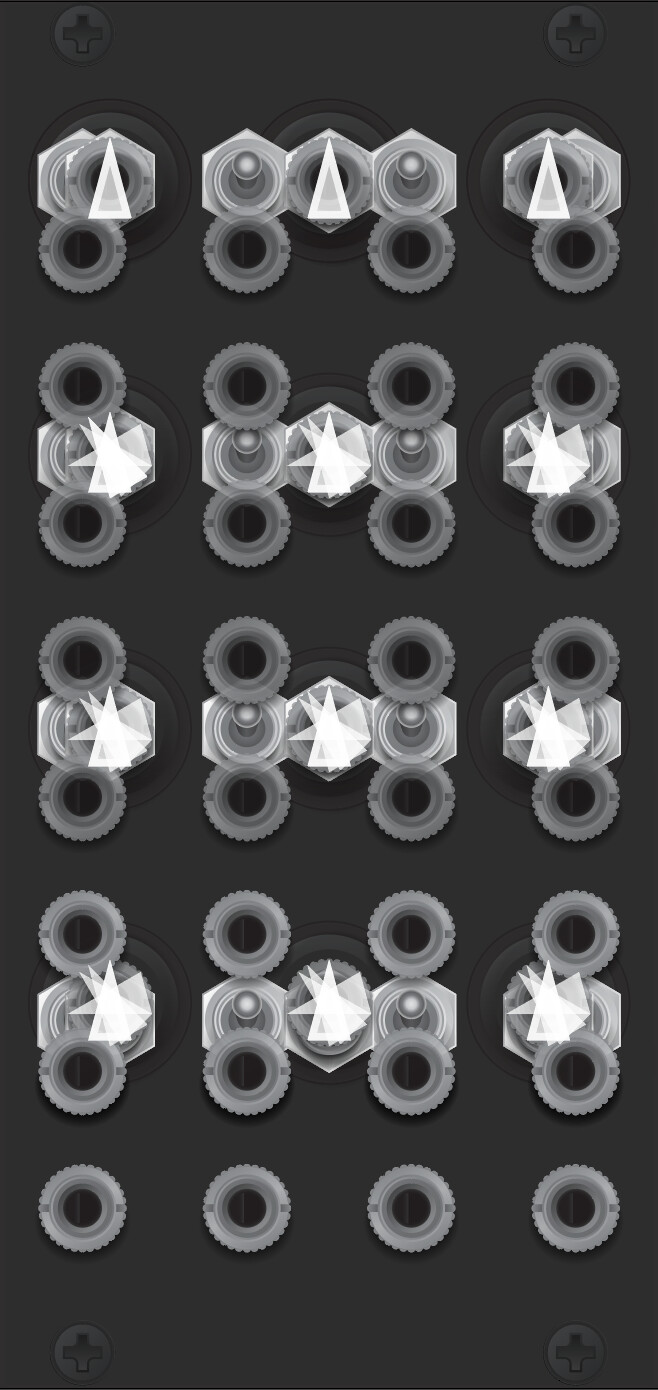
For fun, here’s the “Gen3 Super Grid”, showing valid locations for all component types (with a few exceptions, like the rotary switches mentioned above):

3 Likes

I want the module with one input and 31 outputs, please.

8 Likes

I thought about division, and realized it would make gain amplification on the pots redundant. Dividing by a fraction is the same as multiplying by the inverse of that fraction. The division operator is already a gain amplifier. So the pots can all be +/-1 instead of +/-2. I like this because I prefer a detente position for unity gain. Full extent of the pot is not exactly detente, but it’s predictable enough. Turn that pot hard right and I’ve got a value of one, no mystery.

And of course, what do we do with divide by zero? Really only two choices, either output nothing or output the maximum voltage of the module, presumably 10V. The latter makes more sense from a workflow perspective, it would be shocking to the user if the signal suddenly cut from its near-maximum to nothing. Either way, it’s mathematically wrong; divide by zero is illegal, which is possibly one reason why we almost never see division in an analog module.

I hadn’t thought about subtraction being redundant. I guess it is. But it might make sense to leave it there, it makes the arithmetic simpler for non-mathy types like me to comprehend at a glance. E.g. 1 - 0.5 is easier to grok intuitively than -0.5 + 1. And since subtraction is not commutative, the patch topology affects the outcome, which, again, is more intuitive for subtraction. For me at least.

2 Likes

Thought some more about this and realized that the pots should generate static voltage in the absence of an incoming signal. Opens up many possibilities, e.g. now we don’t need bias anymore, at least for some use cases.

Also realized that with one more feature, this becomes a full-blown traditional color corrector: a gamma function.

2 Likes

Back to the YUV workflow… if I set the dip switches on ESG3 to encode RGsB instead of YUV… does that mean no colorspace conversion is happening? And then, in turn, can I plug YUV in to ESG3 and get YsUV out? Are the voltages going to be wrong for standard broadcast YUV? If so, can I correct for that using the pots?

If this crazy scheme works, theoretically I could have an all YUV path with the currently available modules. Take Y out of TBC2, patch U and V directly into the system. Only issue is the delay on Y introduced by the frame store.

Yes it does, but blanking and black/white level clipping is still happening on all 3 inputs. So that means anything below 0V is going to be clipped. Since UV are bipolar voltages, that means the negative half of the range will be clipped off. You could offset them using the proc amp, but that sets the black level at the negative minimum, making any receiver’s DC restoration circuit registering minimum = center in value. So maybe it’s possible in some cases to rig it to work?

So unfortunately, we’d need to have a YUV input mode for the black/white clippers on the UV channels in order for this to work as a YUV in → YPbPr output mode.

I’m excited to get back to the brainstorm above, but this week is kicking my ass in the lab! So have not been able to check in here as much. Maybe we can start a separate thread for that in the near future. In general though, I love the way this may be taking shape as a kind of “color corrector instrument.”

4 Likes

Solarium, here we come…

5 Likes

Thanks Lars, I know you’ve got huge demands on your time and I really appreciate you answering my questions!

1 Like

hi all, hope you’re good

#1 is there a way to exactly dial in a rgb value?
(#2 esp. into Expedition?)
or #3, link the color directly to the frequency of audio oscillators/LFO’s, from a music eurorack system?

a kind and talented inspiration said to me, “I think what you might want to do the above is a very precise multi channel programmer- something digital that can control down to .01 of a volt… something similar to the buchla 251e. Say you had 4 channels of output per step- you could program the note frequency on one channel, specific RGB values into the other three”

#4 has anyone achieved similar, by any means? how does the that (or the above) patch into LZX?

“if at first you don’t succeed… come on here and ask!”
cheers and best wishes